Who doesn’t want more efficiency and cost-effectiveness? Prioritizing moldability during the design process can help achieve these goals. Here are five key design-related tips to ensure molded parts are manufactured to ideal specifications.
1. Get Down with the Wall Thickness
As a general rule of thumb, uniform wall thickness in part geometry is ideal to ensure the part cools and hardens evenly. While that isn’t always possible, making sure that parts meet the minimum thickness requirements can ensure a sidestep to unsavory side effects such as cracking, warping from uneven cooling, incomplete filling and more. On the other hand, parts with walls that are too thick are susceptible to sink, warp and porosity, so it’s a fine balance. Be sure to check out the appropriate minimum and maximum wall thickness guidelines, which differ by material.
2. Is it Drafty in Here?
It’s best practice to incorporate slight angles, or draft, in part design to allow the finished part to easily eject from the mold without causing strain or damage to the part or mold. It is relatively easy to include draft in the design, and it’s worth the trouble. We recommend at least 1 deg. of draft for parts that will be molded. Keep in mind that design details like wall thickness and material choice all factor into how much draft is needed for your part. Guidelines for draft on injection-molded parts can be found on Protolab’s website.
READ MORE: 8 Tips for Designing 3D Printed Parts
3. Bend Radii Forever
In injection molding part design, forgoing any unnecessary sharp corners is best. Liquid resin naturally wants to flow within organic shapes. If a part includes severe angles, softening these with radii is recommended to ensure your part cools evenly and ejects cleanly from the mold. Incorporating radii in molded designs helps create strong, high-quality and cost-effective parts. If a part must include sharp corners, make sure that the material selected supports that. Some are more forgiving of sharp angles than others. In summary, don’t cut figurative corners in your molded design. In the literal sense, do cut corners by incorporating bend radii.
4. Gate and Pin Placement
Although it might seem obvious, molded parts require designed gates. These enable the liquid resin to flow into the cavity. Standard single-cavity molding and quick-turn molding default to the tab gate.
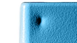
Ejector pins help push the finished part out of the mold. In molding, there’s typically a show side and a non-show side. In general, the non-show side (usually the interior of a part that isn’t easily seen) is a good choice for ejector pin placement versus the exterior show side. The goal is to ensure that ejector pins are orientated to minimize impact on the part. Based on part geometry, the engineering team will propose pin and gate placement to review and approve before a part is manufactured.
5. Use Industry 4.0 Tools to Perfect Design
Picture this: The CAD file for a molding project has reached near maturity—draft incorporated, wall thickness in range, sharp corners avoided, and gate/pin placement hidden. Good to go? Utilize automated AI-powered Industry 4.0 tools to be sure. Upload a CAD file for automated design for manufacturability (DfM) analysis upon part upload, which will visually highlight any areas in the part design that could be problematic and cause issues during molding. Additionally, Protolabs’ Injection Molding Toolkit includes the six most common design flaws as well as actionable tips on how to correct them.
Lucas Tofteland is senior injection molding manager at Protolabs.


