Download the .PDF of this article.
Additive manufacturing is a process that adds material, usually on a layer-to-layer basis, to make a 3D object based off the interpretation of 3D computer-aided-design (CAD) data. Additive manufacturing is also called 3D printing or rapid prototyping.
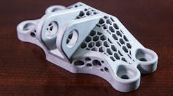
Direct Metal Laser Sintering (DMLS) is an additive manufacturing method that builds prototype and production metal parts using a laser to selectively fuse a fine metal powder.
Traditional manufacturing techniques remove material from a piece of stock to create the desired geometry. Additive manufacturing is capable of producing highly complex features and all-in-one assemblies that would be difficult to achieve with subtractive manufacturing techniques.
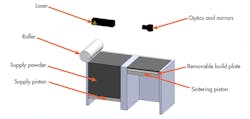
This image shows the main components of a DMLS 3D printer.
Step by Step
Step 1: Material Feed: Supply piston moves upward, placing powder in front of the roller.
Step 2: Adding a Layer: Roller moves across supply piston, delivering powder to the sintering piston.
Step 3: Sintering: Laser sinters the cross section of each part being built.
Step 4: Piston Movement: Sinter piston moves down the thickness of one layer.
Step 5: Layering: The process is repeated until the parts are fully sintered.
Step 6: Part Removal: Sinter piston rises up, allowing the build plate to be removed.
Uses
DMLS creates fully functional parts out of metals such as cobalt chrome, ctainless steel, titanium, Inconel, and many others. The typical users of DMLS fall under these needs:
- Fast turnaround—DMLS parts are often produced in one to three days.
- High complexity—Difficult-to-machine parts, custom medical pieces, hollowed or lightweight parts, and artistic pieces fall in this category.
- Rapid or continuous revisions—Product development efforts and iterative designs are well-suited to DMLS because there are no setup costs as in traditional manufacturing.
Part Complexity
A key advantage of DMLS is the ability to produce parts that cannot be made using traditional manufacturing techniques. Manufacturing with DMLS can be advantageous if engineers design parts with complex geometries, such as integrated fastening features, long and narrow channels, custom contours, and metal mesh structures. DMLS allows for production of assemblies in single-part form reducing number of parts, assembly time, and opportunity for failures.
In specialized applications, the weight of the part is an important criterion of the design. Using subtractive processes for manufacturing of metal mesh or weight-reduced parts will dramatically increase the manufacturing time and cost due to the amount of material removed. DMLS is an optimal process for these parts as both manufacturing time and cost are reduced as volume decreases.
Speed
Speed is an important aspect of the design and manufacturing process. Both the quality of the product and the overall time to market are driven by the ability to produce physical models in a timely manner for fit and function tests, peer review, and market feedback.
Here, additive technologies allow for faster and more efficient concept review and prototyping. Thus, DMLS parts are commonly used during pre-launch activities for product testing, whereas the final product is made with a tool (i.e., die casting, metal injection molding, sand casting). DMLS parts are commonly used to validate designs as part of final product quality assurance as well as stand in for parts early in product life.
DMLS parts do not require tooling (e.g., molds, jigs, fixtures, gauges, etc.), which reduces initial part manufacturing lead time from months to days. Thus, additive technologies such as DMLS present a tremendous value for product customization and change by offering ways to create short-run, customized products without incurring expensive tooling changes.
High Volumes
When considering a manufacturing technique, some of the factors to consider are lifetime volume and the ability to make changes to the part. If a part design is stable, unchanged throughout its lifetime, and the quantities are high, traditional manufacturing processes are less expensive. This is especially true for simple designs that cannot benefit from the geometric complexities that DMLS is capable of producing.
Limited Build Size
DMLS machines come in various build platform sizes. Two of the more popular build platforms are 4 in. × 4 in. × 3 in. and 10 in. × 10 in. × 12 in. While these build sizes are large enough to build a wide array of parts, larger parts (often the ones made in lower quantities) are still not able to fit within the build envelope.
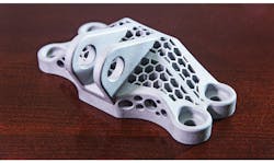
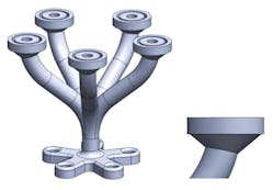
A geometrically complex DMLS part.
DMLS, being a 3D-printing process, is falsely associated with the simplicity implied from other 3D-printing processes.
Preparation of the design before being sent to the DMLS machine and the post processing afterwards can be time consuming. All modern manufacturing processes have before and after steps. CNC, for example, requires the programming of tool paths, machine setup, cutting and grinding, then polishing and de-burring afterwards.
Prior to being sent to the DMLS machine, part support structures are designed and built. This step may take up to an hour and may determine success or failure the job.
DMLS post processing consists of:
- Removing the part(s) from the build plate with a band saw, wire EDM, or handheld rotary cutoff tool.
- The support structures are then removed from the part using hand tools or CNC machining.
- Other optional finishing steps:
- Polishing
- Grinding
- Machining—turning, milling, facing, tapping
- Heat treatment
Support Structures
DMLS parts need support structures for:
- Anchoring the part to the build plate
- Reducing or eliminating warping
- Supporting overhanging geometry
Unlike other laser and powder based additive technologies, DMLS parts move around in the build envelope if not properly secured to the build platform. Movement of the part occurs from the act of spreading a new layer of powder over the previously sintered layer or larger cross sections of the metal part warping during the sintering process. Movement of the part during the build will cause failures in part accuracy and could potentially lead to machine crashes.
A further reason support structures are required is to support overhanging geometry because the spreading would move unsupported overhands. Examples of these types of geometry are horizontal surfaces, large holes in the horizontal access, angled surfaces, arches, and overhangs.
Note: Several methods are employed to support overhanging geometry. Depending on the part and surrounding features, each method has its positives and negatives.
Force from the roller may cause tall, narrow parts to shift in the build. Support structures prevent parts from shifting in the build. Overhang geometry may require support structures to successfully build using DMLS: Horizontal surfaces, angled surfaces <30 deg., arches, and overhangs, large holes on the horizontal axis.
Part Strength During the Build
During the build process, parts are subjected to forces from spreading and compacting of new layers. Tall, thin parts are susceptible to these lateral forces, causing inaccuracy in the parts’ features due to improper design or lack of support structures.
Load-Bearing Features
Load-bearing part features require further guidelines for height to cross-sectional ratios to ensure feature integrity not presented in this article. Generally, as the height of the feature increases, so does the wall thickness.
Distance Between Features
During the DMLS process the laser creates a melt pool that is slightly wider than the laser diameter from heat dissipating into the surrounding powder. This will cause features that are close to each other to bond together or create a section of sintered powder that cannot be removed from between sintered areas in the part. Distance between features should be at least 0.4-0.5mm to adequately remove powder and allow for part movement.
Accuracy
Positive features hold an accuracy of 20-150μm without any post processing. Negative features, such as holes smaller than 50mm, will typically be slightly undersized by 100- 150μm.
Surface finish will vary from material to material, however an unfinished part will have a surface finish of μm RA from 2-5.
How to Use this Information to Influence Your Designs:
The quoted price of parts is heavily influenced by factors such as support structure design and removal of support.
Therefore, minimizing the amount of support structure required will decrease design time, build time, and post processing required.
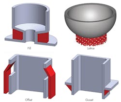
The best way to accomplish this is to make the geometry as self-supporting as possible:
- Design angles to be ≥ 30 deg.
- Utilize chamfers and fillets on corners and features
- Implement features for weight and volume reduction
Example #1:
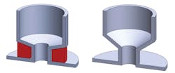
In this example the flanges toward the top of the part will cause a problem. The bottom-facing surface of the flange will require some form of support. Adding a chamfer or a fillet to the overhanging geometry makes it self-supporting.
Example #2:
In this example the sloping angle of geometry is changed, making it self-supporting. Note that angles from 30 deg. to 45 deg. will self-support with some surface roughness and angles >45 deg. will have a smoother surface finish.
Example #3:
The price of DMLS parts is heavily influenced by build time and the amount of material being used.
The surface area to volume ratio of a part plays a large role in determining the quoted price of a given part. A part with reduced mass allows for a lower price because it takes less time to build, uses less material, and has a higher success rate of being produced correctly the first time.
As the volume of a part is decreased, either by redesign or by using another manufacturing process to create the geometry, the overall part price will go down significantly. In this example the important features of a mold are built using DMLS and the surrounding material is milled to save on overall assembly cost.
Example #4:
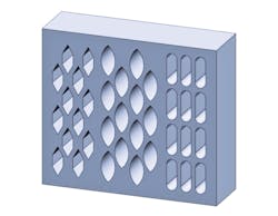
Reduce mass and volume by using self-supporting features in the vertical axis.
