An Engineering Refresher: Mohr’s Circle and Where it Fits into CAD
In a world where software analysis has taken over, let us take a history lesson to remember what makes our finite-element-analysis (FEA) software tick. Morh’s circle is just a graphical representation of shear and stress to obtain information for failure theories in order to calculate if a design will be able to handle a loading scenario. These are the same stresses and theories used in FEA software.
This simplified refresher will show a static two-dimensional loading scenario. Simple drawings such as beam diagrams or other models help to locate high levels of stress. Generating a stress element for these areas of high stress will simplify the calculations to one or few points of interest.
It is impractical to test all materials for all combinations of stresses and loading situations. Varignon’s Theorem or the principle of transmissibility can help draw or simplify stresses in these diagrams and stress elements; for rigid bodies, Varignon’s theorem and the principle of transmissibility may simplify diagrams.
Varignon’s Theorem: The moment of a force about any point is equal to the sum of the moments produced by the components of the force about the same point. This means a force, or moment acting in an arbitrary point in space, can essentially be moved to a more convenient location.
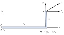
MO = FyxA − FxyA
The right hand rule—if you mimic the moment with your right hand, the force is positive if your thumb is up and negative if your thumb is down. FxyA would turn clockwise, and when mimicked with the right hand your thumb will be down, making the moment negative. This is not used in all examples. A later example will be done in the opposite manner to show that, as long as you stay with one direction of rotation as positive and the other as negative—and don’t change—the numbers will work.
Principle of Transmissibility: In a rigid body, a force is able to be moved anywhere along its line of action. This can simplify forces of a moment to one axis.
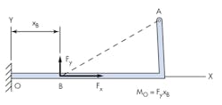
MO = FyxB
This line of action could also continue to the y-axis, and then MO would equal the force of FxyB. With an understanding of the loads acting on an area, a stress element can represent points of interest—or perhaps better worded, points of failure. Mohr’s Circle is a learning tool to help visually show stresses and explain failure theories.
Understanding Material Properties
Material properties are important to designs, which is why CAD software includes libraries of materials. While strength might indicate whether or not the design will work, a material’s ductility will help indicate which failure theory to use. Ductile materials are defined as having more than 5% elongation before breaking; brittle material presents less than 5%. Looking at a stress-strain diagram of a brittle material, the plastic region is absent before breaking and the yield point is difficult to define.1
For example, a ductile material under a static load may use the yield strength (for uniaxial stress), the maximum shear, or distortion energy method (for multi-axial stress). Brittle material may use a modified Mohr’s method. If continuing with a ductile material under static load, Mohr’s circle can help minimize errors and offer a visual for stress conditions and points of interest while answering the following:
- Maximum and minimum principal stresses, and the direction in which they act.
- Maximum shear stresses, and the orientation of the planes on which they act.
- Normal stresses that act on planes where the maximum shear stresses act.
- Normal and shear stresses that act on an element with any orientation.2
Stress Element
Mohr’s circle often is taught by starting with a stress element. This is an isolated element in areas of high stress in a model. A vector will represent the stresses on each side of the element. A Mohr’s circle can then be draw from the element. Using the following stress element:
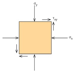
Where:
σx = −32ksi
σy = −22ksi
τxy = −10 ksi (counterclockwise −ccw)
τxy = 10 ksi (clockwise −cw)
This example is not following the right-hand rule.
Step 1: Each face of the 2D element is a plot on the graph. The first coordinate will be (−32, −10), which is the right face of the stress element that shows σx and τxy rotating ccw. Next is the top face of the stress element (−22, 10), from σy and τxy cw. These two plots make the diameter of the first circle. Drawing a circle using this diameter will intercept the x-axis twice, forming the first two principle stresses.
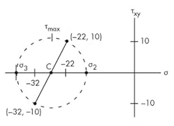
This is only a 2D example, with zero stress in the z-axis − σ1 = 0. Therefore, the next circle is drawn between σ2 and σ1. This means the final circle is drawn using σ2 and σ3.
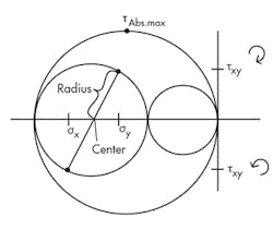
From this you now know the center, the principle stresses, and the absolute maximum shear. It is possible to calculate the same information.
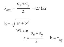
Center (σAverage)= (σx + σy)/2 = 27 ksi
This example Radius will be calculated by:
Radius = [(Square root)(Center − σy)2+ (τxy)2] = 11.18 ksi
In some examples, the radius will be the maximum shear. However, for this specific example, the larger circle will carry a higher shear value, called the absolute maximum shear, and is calculated later in the article.
σ3 = Center + Radius = −38.18 ksi
σ2 = Center − Radius = −15.82 ksi
Remember, in this example, the center is negative and a radius is an absolute (positive) number.
σ3 will be the diameter of the large circle. This means the absolute maximum shear will be the radius.
τAbs.max.= σ3/2 = 19.09 ksi
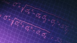
Then using the principle stress or applied stresses can be used to find von Mises stress.
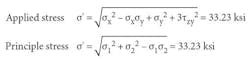
Applied Stress σ'=[(square root) σx2 − σx*σy+σy2+3* τxy2] = 33.23 ksi
Principle Stress σ'=[(square root) σ32+ σ22 − σ3*σ2) = 33.23 ksi
To demonstrate how important selecting and knowing what failure theory is needed, both the distortion energy method (NDEM) and the maximum shear theory (Nτ) will be calculated. For this example, A36 steel is used.
NDEM = Sy/σ' = 1.08
Nτ = Ssy/τAbs.max = 0.943
Where
Sy = Yield Strength = 36 ksi
Ssy =Shear Yield Strength (estimated to be half Sy) = 18 ksi
Using the distortion energy method, the design will work. However, it could fail if it needs to meet a standard in which the maximum shear stress was used.
The Benefits of Software Analysis
While software has added FEA features that incorporate failure theories, it is important to understand the engineering behind them: material properties, loading scenario, standards, and other phenomena. Entering numbers into a program while not knowing what failure theory is being used in the software—and if the design requires a particular theory—can be dangerous and a liability.
For uniaxial tensile strength, the Tresca Criteria, also called the Maximum Shear Theory, is more conservative than von Mises, also called the Distortion Energy Method. Standards might require a design to use the more conservative theory. This is why it is important to know what theory your FEA package is using. Some FEA software allows users to change the failure theory if needed.
Despite the occasional risk or possibility for error, software is a handy way to back up or double-check a design. CAD programs do help to determine the actions and reactions of loads. FEA and simulations are doing great things for calculating potential problems that may occur in loading. While Autodesk and PTCreo have free trials, a quick internet search should show that Wikipedia has recently (January 30, 2017) updated a list of free online FEA software packages. You don’t have to spend a lot, or anything, to double-check your work with FEA software.
The benefit to using software to double-check design is speed and iterations. When models have non-linear geometry, change parameters, or are subject to creep, software can help calculate changes and complex geometries quickly. When starting something new, ask colleges and others that have more experience with how software is used, or what failure theory is best. Online videos and tutorials are offered on many of the CAD company’s websites or video hosting sites, such as YouTube. If you are new to the software, or it is an unfamiliar application, start simple. Try altering the failure theories, loads, materials, etc., to get a handle how changes affect the model.
Quick changes are also where having an experienced engineer will be necessary. Engineers should not underestimate their education. They still must understand materials and loading scenarios to judge if a model or result of a load seems correct. Engineers need to recognize if a result seems wrong, so they know to look into the program to see if something was entered incorrectly. Users should never blindly accept whatever the software comes up with.
References
Norton, R.L. (2006). Figure 5-17 on page 194 (3rd ed.). Upper Saddle River, NJ: Pearson.
Norton, R.L. (2006). Page 34 ductility and brittleness, page 234 5.4 stress concentration (3rd ed.). Upper Saddle River, NJ: Pearson.
(2) Mott, R.L. (2004). 4-3 Mohr’s circle page 145 (4th ed.). Upper Saddle River, NJ: Pearson.
Mott, R.L. (2004). 5-7 design factor page 185-186 (4th ed.). Upper Saddle River, NJ: Pearson.

About the Author
Jeff Kerns
Technology Editor
Voice Your Opinion!
To join the conversation, and become an exclusive member of Machine Design, create an account today!

Leaders relevant to this article: