Isolated voltage sensing for safe control
Resources:Avago Technologies, www.avagotech.com/ Optoisolators in alternative energy HCPL-7840 isolation amplifier data sheet HCPL-7800A/7800 isolation amplifier data sheet ACPL-C87B/C87A/C870 Precision optically isolated voltage sensor data sheet Compressor and motor burnout video, http://youtu.be/GP0jEaNIypE Another electric motor fire video, on an e-bike |
Electric motors that are either poorly maintained or which lack the proper electrical protection are the second greatest cause of electrical fires. So says the Factory Mutual Research Corp., a nationally recognized testing laboratory that tests and certifies electrical equipment.
No surprise, then, that safety is a prime concern when designing industrial motor drives, which can involve high voltages and currents. In particular, most drives incorporate an inverter circuit which rectifies ac into a high-voltage dc signal, called a dc link which, in turn, serves as a power supply for circuitry that generates drive signals to power the motor. The dc-link voltage must be continuously controlled. Under certain operating conditions, a motor can act as a generator and deliver a high voltage back into the dc link through the inverter’s power device and/or the recovery diodes. This high voltage adds to the dc-link voltage, and the IGBTs (insulated-gate-bipolar transistors) driving the motor can be stressed by a high — and potentially damaging — surge voltage.
Modern optical couplers used to monitor the dc link can easily detect such overvoltages. Ditto for detecting undervoltage conditions as caused by an overload on the power grid or loss of a power phase, both of which are common conditions.
Motor drives aren’t the only applications that require isolated voltage sensing for safe, robust system control and protection. Other uses include solar inverters and uninterruptible power supplies (UPS). In all these cases, a sensor must accurately measure the high dc-link voltage and provide galvanic isolation between the hazardous high-voltage side and the low-voltage controller side which sits in the neighborhood of system operators. An isolated voltage sensor can also serve in isolated temperature sensor designs and in 0-to-10-V analog control protocols. Here, the voltage sensor must linearly and accurately measure the temperature or control signal and send it across the isolation barrier thus providing insulation as a safety measure and eliminating ground loops.
Optically isolated amplifiers have been specifically designed for shunt-based current-sense applications, where an input voltage range of ±200 mV (full scale ±320 mV) is adequate. But these amplifiers typically have a small dynamic range so it is difficult for them to sense low-level signals in the presence of high voltages. Thus, there has been a need for isolation amplifiers that operate over a wider dynamic range.
Recently, optical isolation amplifiers have been designed with a nominal input range of 0 to 2 V to handle voltage-sensing applications. Besides an improved input-voltage range, the new isolation amplifiers sport a 1-GΩ input impedance compared to the 500-kΩ input impedance of earlier models, a 2,000× improvement. The high input impedance drastically reduces the error caused by signal source loading.
How optical isolation amplifiers work
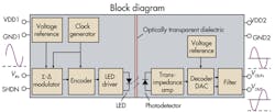
A review of isolation-amplifier functional blocks shows that the amplifier first senses the input voltage (single-ended analog signal) and converts it to a digital bit stream. The bit stream then transmits across the optical coupling pair consisting of an LED and a photodetector. This optical signal path provides the electrical insulation barrier. Because the transmitted signal is optical rather than electrical, it is immune to magnetic fields and electrical noise. The photodetector recovers the optical signal and converts it back to an electrical signal, which is decoded and filtered to reproduce an analog output signal. The output voltage, provided in differential mode for better common-mode noise rejection, is proportional to input voltage with unity gain.
The isolation amplifier is available in three gain accuracy options: ±0.5, ±1, and ±3%. It also is housed in a stretched SO-8 package which is 30% smaller than the DIP-8 package that’s normally used. All amplifiers have a double protection rating of 5,000 VRMS/1 min per the UL 1577 safety standard. The 1,414 VPeak maximum working voltage specification per IEC/EN/DIN EN 60747-5-5 ensures circuits on the low voltage side are unharmed by hazardous high voltages.
Designers using the isolation amplifiers as isolated voltage sensors first select resistors to form a voltage divider that scales down the voltage to a level within the sensor input range. The application circuit is significantly simpler than alternative approaches that employ separate devices for sensing and isolation. Typical applications include isolated voltage sensing in ac and servomotor drives, isolated dc-link voltage sensing in solar and wind-turbine inverters, and signal isolation in data-acquisition systems.
In motor drives, the dc-link voltage must also be continuously controlled. Under certain operating conditions, a motor can act as a generator and deliver a high voltage back into the dc link through the inverter’s power devices and/or the recovery diodes around the power devices. This high voltage adds to the dc-link voltage, and the IGBTs are stressed by a high — and potentially damaging — surge voltage.
One common condition is an undervoltage caused by an overload on the power grid or loss of a power phase. A wide input range lets isolation amplifier circuits detect such undervoltages. A low linearity error of as low as 0.05% also comes in handy for this application. For example, a designer may set a threshold 20% lower than nominal dc-link voltage as an undervoltage condition. This sets a 1.6-V input voltage as the lower limit.
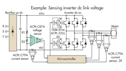
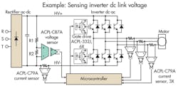
An example of a detailed circuit with an isolation amplifier carrying a wide input range can be seen in the accompanying diagram. Given that the isolation amp’s (ACPL-C87x) voltage sensor nominal input voltage for VIN is 2 V, the designer must choose resistor R1 according to Equation 1:
R1 = (VL1–VIN)/VIN × R2 (1)
For example, if VL1 is 600 V and R2 is 10 kΩ, then the value of R1 is 2,990 kΩ.
There are several ways of choosing resistor values. One method is to combine several resistors to match the target value; for example, 2 MΩ, 430 kΩ, and 560-kΩ resistors in series make 2,990 kΩ exactly. A VIN of 2 V corresponds to a VL1 of 600 V. However, in cases where VL1 is not 600 V, specific resistance values might be difficult to find.
Another selection method is to round the target resistance up to a convenient value, 3 MΩ for example, to simplify resistor selection. In such cases, the scaling relationship may need fine-tuning. In the same example with a VL1 of 600 V, R1 of 3 MΩ, and R2 of 10 kΩ, VIN is solved to be 1.993 V.
The down-scaled input voltage is filtered by the anti-aliasing filter formed by R2 and C1, with a corner frequency of 159 kHz (The value of R1 is usually much larger than R2, so it is neglected in this calculation.), and is then sensed by the isolation amplifier. The galvanically isolated differential output voltage (VOUT+ – VOUT–) is proportional to the input voltage. The OPA237, configured as a difference amplifier, converts the differential signal to a single-ended output. This stage can also be made to amplify the signal and, if necessary, low-pass filter the signal to limit bandwidth.
In this circuit, the difference amplifier is designed for a gain of one with a low-pass filter corner frequency of 15.9 kHz. Changing resistors R5 and R6 will change the gain. The bandwidth can be reduced by boosting the capacitance of C4 and C5. The isolated output voltage VOUT, which is linearly proportional to the line voltage on the high voltage side, can be safely connected to the system microcontroller.
With the ACPL-C87X connected to have a gain of 1, the overall transfer function is simply:
VOUT = VIN (2)
or
VOUT = VL1 / ( R1/R2 )+1 (3)
Cutting power dissipation
The input stage of the application circuit can be simplified. R2 and RIN, the input impedance of the ACPL-C87x, create a current divider that results in an additional measurement error component that adds to amplifier gain error. Assuming R1 and RIN have a much higher value than R2, the resulting loading error can be estimated as R2/RIN.
With an RIN of 1 GΩ for the ACPL-C87x, the loading error is negligible for R2 values up to 1 MΩ, where the error is about 0.1%. Though this error is small, it can be further reduced by lowering R2 to 100 kΩ (error of about 0.01%), or 10 kΩ (error of about 0.001%).
But when R2 is lower, designers must examine the higher power dissipation in the resistive divider string, especially for high-voltage sensing applications. The resistive divider string consumes only 12 mW, giving a 0.01% loading error, with an R2 of 100 kΩ when there is 600 Vdc across R1 and R2. (This assumes a VIN of 2 V.) If R2 drops to 10 kΩ to get the error down to 0.001%, the power consumption rises tenfold to 120 mW. This trade-off between measurement accuracy and power dissipation is a useful design option when energy efficiency is critical, as in photovoltaic inverters and battery-powered applications.
In addition, the ACPL-C87X has a shutdown mode, which can be activated with a high-level logic input on the shutdown pin. In this mode, the IDD1 supply current drops to only 15 μA, making the device a candidate for battery-powered devices and other power-sensitive applications.
Finally, thermistors are widely used to measure temperature. Many designs call for galvanic isolation between the potential of the thermistor and that of the system analog/digital converter, especially when the thermistor mounts near high voltages or in electrically noisy or poorly grounded environments. A lack of isolation can impair safety and induce electromagnetic interference (EMI).
The accompanying diagram shows a simple isolated temperature sensor circuit. RT1 and R2 form a voltage divider from the floating, constant 5-V voltage source that also powers the voltage sensor. Designers choose RT1 and R2 so the voltage fed into the ACPL-C87X isolation amplifier does not exceed the full-scale range of 2.46 V. The high-impedance input terminal of the ACPL-C87X allows use of a relatively high R2 resistance without causing a significant loading error. Designers select the resistor and capacitor values after reviewing the data sheet for the thermistor.
Edited by Leland Teschler, [email protected]


