Stepper Motors Step Up for Machine Automation

Download this article in PDF format.
Engineers rely on motion-control devices to improve efficiencies and production rates on automated factory floors, or at least maintain them. One family of such devices, stepper motors, is widely used because of their simple implementation, attractive price/performance ratio, and high torque at low speeds. In the past, stepper motors couldn’t keep up with servo motors in demanding applications, but recent advances have greatly upgraded stepper-motor performance, expanding the areas in which they can make positive differences.
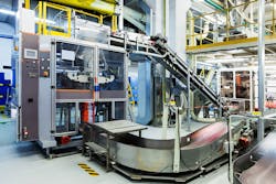
Stepper motors are often used in demanding applications, such as this packaging machine.
Here’s a look at those advances, and an overview of the other two leading motion-control devices for machine automation: servo motors and variable-frequency drives (VFDs).
The Top Three Motor/Drive Types
Engineers can choose from numerous varieties of motors, drives, and controllers to meet the demands of the application at hand, such as torque, speed, and size.
Stepper motors generally include a motor, drive, and controller. The motor, a brushless dc version, moves in equally sized fixed steps during rotation, and only rotates one step at time. Stepper motors have simple designs and controls, and don’t require tuning or adjustment. They provide excellent torque at speeds under 1,000 rpm and are one-half to one-third the cost of comparable servo systems. Their output torque decreases as their speed (rpm) increases, making them difficult to operate. Not only that, it’s tough to get useful work out of them at speeds above 1,000 rpm for dc-powered applications and above 1,500 rpm for ac-powered ones.
Servo motors consist of a motor, drive, controller, and a positional feedback device. They can deliver high torque at speeds above 2,000 rpm, and are preferred over stepper motors for variable load applications. They are also more complex to control than stepper motors and require tuning and adjustments. Position feedback, together with upfront plus maintenance costs, push their prices above those of stepper motors. At about $2,000 (USD) per axis, cost is considerably higher than stepper-motor systems.
VFDs include an ac motor and a drive and cost less than steppers or servo motors, but cannot provide positioning. They do, however, offer good speed control, even with variable loads. A VFD also saves energy in applications where the motor does not need to run continuously at full load. Furthermore, VFDs have built-in soft-start capabilities to limit inrush currents.
Let’s look at the stepper-motor systems in detail, and show how advances are increasing their areas of application.
Stepper-Motor Systems
The three main elements of a stepper-motor setup are the motor, controller, and drive. These three components are used along with a programmable logic controller (PLC) or a PC, either of which provides supervisory control and coordination among multiple stepper motors.
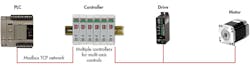
All stepper-motor systems consist of a controller, drive, and motor. Most systems are connected to a PLC for supervisory control.
The controller accurately regulates the step position, the speed at which the motor moves from step to step, and the torque generated by the motor. It generates control signals used by the drive. Stepper controllers can be either open- or closed-loop. Open-loop controllers do not require feedback from the motor, assuming the motor is at the commanded step position and producing the desired torque. Closed-loop controllers use feedback based on the motor load, resulting in performance closer to a servo motor.
The drive amplifies and modifies signals from the controller to regulate the magnitude and direction of the current flow into the motor windings. Thus, it drives the stepper motor to its desired positions, and holds it there with the desired amount of torque.
The stepper motor has several coils that must be energized in a specific sequence to make the motor rotate through each step. Typical stepper motors move 1.8 degrees per step, which equates to 200 steps per 360-degree revolution. Some stepper motors move in smaller steps to provide more precise positioning. For example, at 0.9 degrees per step, there are 400 steps per 360-degree revolution.
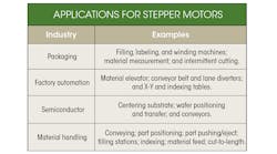
Stepper motors are a good fit for many linear manufacturing processes because of their repeatability, high torque at low speeds, and minimal required maintenance. Common linear-positioning applications include conveyers, rail positioning, and X-Y tables.
Stepper motors also work well in rotary-motion applications, thanks to their versatile mounting options, repeatability, and reliability. Common rotary-motion applications are indexing tables, cut-to-length machines, and labelers.
Combo Unit Benefits
Advances in technology along with end-user demands have led to combining the three main components in three different ways: drive and controller; drive and motor; and drive, motor, and controller.
These combo units offer several manufacturing benefits. They have smaller footprints than separate units, thus saving space. And there’s less wiring among the two or three components—none when using a controller, drive, and motor combo —so installation costs and the risk of incorrect wiring are lower. Here’s a closer look at the advantages of the three combo units.
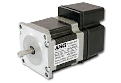
This AMCI stepper combo unit from IDEC houses the controller, drive, and motor in one compact package.
Controller and driver: Eliminates wiring between controller and drive. This unit receives instructions directly from a PLC, and works well with a wide range of stepper motors. The combination of controller and drive is a good choice for motion-control applications involving more than one axis of stepper-motor control, as there are versions on the market that handle up to six axes of motion control.
Drive and motor: Removes the drive from an enclosure, reducing the required space and amount of heat generated. This can result in smaller enclosures and possibly eliminates cooling components such as fans, heat exchangers, and air conditioners. High-volume applications get the biggest bang for the buck from the motor/drive combination because it simplifies design without reducing performance. It also lowers total cost and guarantees component compatibility. Some vendors offer these combo units in industry-standard motor frame sizes such as NEMA 17 or 23.
Controller, drive, and motor: This fully integrated stepper motion system eliminates cabling among the controller, drive, and motor. It provides the most reduction in enclosure space and heat generation by removing the controller and drive from the enclosure. It is the most compact and least expensive option of the three combo units.
PLC/Stepper-Motor Communication
Whether opting for separate components or a combo unit, a PLC or PC is still needed to provide supervisory control and coordination. Most stepper motors are paired with a PLC, a design we’ll now examine in detail.
Automated machines and processes are commonly controlled by PLCs. In addition to real-time control, PLCs also coordinate all of the controlled devices, such as motors, valves, and cylinders, and provide functions including data collection and storage, as well as remote access.
Interfaces between PLCs and stepper-motor controllers can be either via individual inputs and outputs hardwired between the two, or through a digital data link. Hardwired signals require a lot of wiring and corresponding installation labor, which opens up the possibility of wiring errors.
Digital data links, such as the Ethernet protocol Modbus TCP, only require a single cable between the PLC and the stepper-motor controller, simplifying installation. Several stepper-motor controllers can be connected in an Ethernet network, further reducing wiring.
Digital communications are more flexible and let new functions be added simply by reprogramming the PLC and stepper-motor controller, rather than running new wires. The full gamut of stepper-motor controller functions, including control, monitoring, and diagnostics, is typically available via the digital data link, all through a single Ethernet cable.
Simplifying PLC Programming
PLCs must be programmed to command stepper-motor controllers, often a complex task requiring a high degree of expertise. Some vendors offer PLC macro instructions that can be tightly interfaced with the controller software to simplify and speed code generation. These PLCs use prebuilt motion-control macros that only require editing parameters, as opposed to generating code.
Prebuilt PLC macros reduce programming time and effort when pairing a PLC with a stepper-motor controller, as with this Jog macro. Instead of programming, the operator need only set the macro’s parameters.
For example, IDEC’s WindLDR PLC programming software, when combined with the company’s FC6A PLC and AMCI stepper-motor controllers, can be configured with drag-and-drop commands to control up to 12 axes of motion.
Some of the specific commands commonly used when PLCs are paired with stepper motors include:
- CW/CCW Jog Moves: The CW (clockwise) Jog Move increases the motor position count and the CCW (counter clockwise) Jog Move decreases it. These commands are often used to give operators manual control over the axis of rotation. Jog Moves can also control speed instead of position. Running speeds, accelerations, and decelerations of the Jog Move can be changed while the move is in progress.
- CW/CCW Registration Moves: The CW Registration Move increases the motor position count, while the CCW Registration Move decreases it. An additional feature of Registration Moves is that users can program the drive to ignore the Controlled Stop conditions until a minimum number of steps have been made.
- Hold Move: This command can be used with some moves to bring the axis to a Controlled Stop. The move can be resumed and finished, or it can be aborted.
- Blend Move: A Blend Move lets operators string several relative moves together, then run all of them sequentially without stopping the shaft between moves. This function can be run in either direction, and the direction is set when the command is issued. The direction of motion cannot be reversed with a Blend Move.
Recent advances in stepper-motor system technologies are improving efficiency, flexibility, and cost-effectiveness. One of the leading innovations is to use the controller, drive, and motor in various combinations to reduce the required footprint and corresponding enclosure space. Another important innovation is the inclusion of prebuilt macros in the PLC programming software to cut coding time and complexity. Overall, these and other advances help simplify stepper-motor system implementation for a wider variety of applications.
Stepper Motors in Action: Part 1
An original equipment manufacturer (OEM) of various-sized ultrasonic cleaning machines was having issues with mounting its stepper-motor control system. Its engineers wound up spending many hours writing PLC ladder logic from scratch.
The OEM chose to upgrade to an FC6A PLC and IDEC’s AMCI, a combo stepper controller, drive, and motor. This design solved the mounting issues by packaging the controller, drive, and motor in one housing. The combo unit generated a considerable amount of heat; however, flanges on the front of the motor for mounting acted as heatsinks and increased the unit’s life by reducing its operating temperature. The new design also let them use PLC stepper-motor control macros, which cut the cost of ownership by reducing programming time and letting them easily reuse code from one machine to the next.
Stepper Motors in Action: Part 2
A manufacturer was designing a new reflow oven and needed a simple way to control six axes for moving printed circuit boards through the process. The most cost-effective method was found to be an FC6A PLC paired with six AMCI units, each consisting of a controller, driver, and motor. This design was easy to program, thanks to the existing motion-control macros. The combo units’ Device Level Ring function let the company daisy-chain one unit to the next; the overall system would recognize if one of the chains in the connection is broken.
Stepper Motors in Action: Part 3
A machine builder serving the pharmaceutical industry needed a compact tabletop metering machine for dispensing an anesthesia drug by controlling a peristaltic pump. The final machine had to be network-compatible, cost less than an equivalent servo, and work easily with PLCs. It ended up consisting of an FC6A PLC paired with an AMCI combo stepper motor to control the pump. The design offered better value and reliability than other stepper-motor approaches.
Don Pham is Product Manager at IDEC.

About the Author
Don Pham
Product Manager
Voice Your Opinion!
To join the conversation, and become an exclusive member of Machine Design, create an account today!

Leaders relevant to this article: