Lesson 2
The basic limiting factor for electrical devices is prolonged exposure to high temperatures which deteriorate insulation layers, boundary layers in transistors, and other parts. Since generated heat equals R x I2 x t the rating limitation of a motor, relay, or inverter is the RMS value of current. Similarly, the limiting factors of mechanical devices are mechanical stresses — tension, compression, bending shear, and Herzian pressure. The exponent here is not two, but ranges from 3 to 50 and above.
Ferrous material fatigue
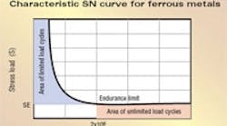
Fatiguing of metallic components is well documented. Cyclically loaded parts fail even when the stress load magnitude never exceeds static strength (which parts can easily endure without damage.) Another well-known phenomenon: If the magnitude of the cyclic stress load is decreased enough, parts can endure unlimited load cycles. This stress level is called the endurance limit. Described by S-N Curve, this behavior is defined in terms of stress and number of cycles.
All major gearbox components are subjected to cyclic stresses, even if external loads are constant. For example, consider gear teeth. With every wheel rotation each tooth becomes fully loaded on engagement; then it passes through the action area, becomes unloaded, and completes a dynamic load cycle. In the case of a sun gear in a three-planet gearbox, this actually occurs three times per revolution due to multiple contacts. Assuming the gearbox is driven by a servomotor at a moderate 2,000 rpm input speed, in an eight-hour period each sun gear tooth endures 2,000 x 3 x 8 x 60 = 2,880,000 load cycles.
Countless tests confirm that for ferrous materials, the exponential relationship between stress S and the number of endured load cycles N that result in no damage actually levels out at the endurance limit — at about 2 x 10⁶ to 107 cycles. This is valid if the part is subjected to bending, shear, tension, or compression. Based on this we can distinguish two distinct areas of the SN relationship:
• The area of limited load cycles — plots situations resulting in limited life. This area shows and exponential relationship between S and N, mathematically described as S = 1 / N1/E = N1/E or N = 1/SE. Because of the large range involved, the relationship is usually manipulated and plotted in its logarithmic form: log S = -1/E x log N or log N = -E x log S.
• The area of unlimited load cycles is the horizontal portion of the S-N curve.
The exponent E determines steepness of the S-N relationship slope. It depends on the alloy, heat treatment conditions, and loading type. E covers a wide range — about six to 80. A comparison in the logarithmic scale allows the slope to appear as a constant linear slope. For a range or set of different stress levels and its frequency of stress level occurrence, damage accumulation calculation methods are used, including the wellknown Palmgren-Miner rule.
However, keep in mind if the number of the load cycles is above the 2 x 10⁶ the stress load has to be at or below the endurance limit; otherwise the component will fail. As shown in the example, for the number of load cycles a sun-gear endures over eight hours (2.88 x 10⁶) the components must be sized and designed to endure unlimited load cycles. Gearbox rated torque must equal the torque level that loads all components at or below their endurance limits.
Unfortunately there is another phenomenon that makes otherwise straightforward sizing less transparent — the bearing. Rolling element bearings behave differently than other components; specifically, they do not have a clearly definable endurance limit. The high-pressure loading between rolling elements and races do not follow the above described endurance behavior. For this reason bearings are typically sized, designed, and rated for a lifetime (say 10,000 hours) with assigned a certain statistical probability of failure (say L10 life, or a 10% chance of failure.)
As noted, the relationship between the load and number of load cycles is exponential, with an exponent of three to 10/3, but with no defined endurance limit. The familiar exponent three is applied to bearing calculations and also to Root Mean Cube or RMC calculations used to analyze complex load cycles consisting of different loads of varying duration.
The exponent of three in this formula is valid for bearings, but isn’t really applicable for the other gearbox components. Specially tailored calculations help identify the exponents valid for teeth, shafts, and other parts.
Gearbox torque rating
The majority of real-world gear applications far exceed 2 x 10⁶ load cycles. For this reason, the recommendation of nearly all gear rating standards — AGMA, ISO, DIN — is to base gearbox torque ratings on endurance limits and minimum bearing life. For industrial gearboxes, AGMA recommends 5,000 to 10,000 hours.
There is only one true rated torque for a gearbox — for continuous duty. Unfortunately for marketing reasons sometimes ill-defined acceleration torques, peak torques, or emergency-stop torques are used as references. Still, only in applications where the number of load cycles is below 2x10⁶ are loads exceeding rated load permissible. The majority of real-world automation applications reach this number of load cycles in a few days, weeks, or in a best-case scenario, after some months of operation. As a rule of thumb:
If the peak load cycle is part of the designed standard working duty cycle of the machinery, the peak load should not be higher than the rated torque unless the machinery is only working a very limited time. An hour of operation a day qualifies.
Another situation where peak loads can exceed rated torque is if the user and OEM do not expect extended, maintenance-free life. Since simple RMC calculations are not applicable to other internal gearbox components in such cases, data should be submitted to the manufacturer.


