The need to produce lighter and more performant products has lead all industrial branches to continuously seek innovative approaches in the fields of materials development, manufacturing systems engineering, and processing technologies. Scientific research and successful industrial case studies alike show that the high-performance requirements of innovative hybrid products can only be met if the material properties are ideally adapted to the requirements, load profile, and function of each individual component.1
Multi-material joining is pervasive in automotive industry components and has been extensively researched. Other sectors—such as heating and cooling, or electrical and electronic applications—can also benefit from optimizing products by integrating multi-material solutions. Unfortunately, a lack of high-performance and cost-efficient multi-material joining technologies has prevented a wider application.
When looking at multi-materials joining, especially between metals, one of the most relevant materials is copper. Currently, copper is widely used in the fields of heating and cooling equipment and electrical and electronic devices because of its excellent thermal and electrical conductivity. Another big advantage is that, as a semi-precious metal, copper features high chemical resistance, meaning it is a very stable metal during contact with other materials or chemically aggressive media (e.g, cooling fluids). These properties make it a technologically ideal material for numerous applications related to electrical, electronic, electromagnetic, heating, and cooling applications.
This is also reflected by the demand for copper, which has been increasing over the last several years. Consequently, the price of copper price has also been increasing significantly; it is now more than three times higher than the price of aluminum (~$6,965/ton). Another drawback to be accepted when applying copper is its enormous density of 8,96 g/cm³, leading to a high weight of the component and conflicting with current trends of weight reduction that are substantiated by environment sustainability demands.
Solving the conflict of interests between the technological benefits and the disadvantages is possible by a partial substitution of copper. Therefore, many companies have come together to start the JOIN’EM project. The project is looking for components currently made completely out of copper that will find benefit in being substituted by copper-to-aluminum or copper-to-steel hybrid parts. The materials should only be kept in the sections of the component where copper is indispensable to achieve the technological function or performance—e.g., as a local thin copper layer.
This approach helps to significantly decrease the consumption of copper as a high-cost material, but it necessitates high-quality connections of copper-aluminum and copper-steel parts. Thus, there is a clear need for joining technologies suitable for manufacturing high-quality dissimilar metal joints. They must fulfill the application-dependent requirements without needing additives or containing expensive, critical, or hazardous materials.
In particular, copper-to-steel tubular connections are found as part of a refrigeration circuit of compressed air-dryers, which are used in all cooling applications. A refrigerant gas/liquid flows at the inside, while the outside is exposed to the ambient conditions of an air-compressor room (up to 113°F/45°C). Moreover, such connections are also used as an inlet pipe of a compressed air-dryer, through which compressed air that is saturated with water vapor flows (approximately 95°F/35°C).
Joining of aluminium-to-copper and copper-to-steel connections in both tubular and sheet configuration can be accomplished through the electromagnetic pulse technology. The benefits of this solid-state welding process include:
- No additives or filler materials required
- No heating
- Suitable for high-volume production due to short process time and high production rate
- Environmentally and operator friendly
It is based on a high-speed collision of the two joining partners. For the process, at least one of the joining partners is accelerated by electromagnetic forces applied via a so-called tool coil. As a consequence, the joining partners impact with each other, and if the collision parameters are within a suitable range, the welded joint occurs.2 The main requirements for the joints in the refrigerating circuits are the leak tightness of the joint during the lifetime of the air-dryer, which can amount up to 20 years, as well as avoidance of corrosion of the joint.
Copper-to-Steel Joints
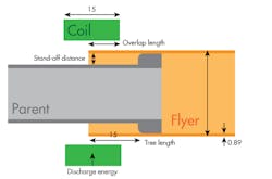
One of the first set of experiments within the JOIN’EM project was on copper-to-steel tubular joints, using copper tubes and cold worked carbon steel rods and tubes. The copper tubes had an outer diameter of 22.22 mm and a wall thickness of 0.89 mm. The outer diameter of the internal steel workpieces was chosen to obtain a stand-off distance of 1.0, 1.5, and 2.0 mm. Solid rods as well as tubes with a wall thickness of 1, 2, and 3 mm were used as internal joining partners. The tube-to-tube specimen configuration is shown in Fig. 1.
1. Tube-to-tube specimen configuration
One of the requirements for specific industrial applications, as mentioned before, is the leak tightness.
Experimental studies carried out in JOIN’EM have shown that with regard to leak tightness, the stand-off distance is a decisive parameter. Tube-to-rod specimens produced with a stand-off distance of 1.5 and 2 mm passed the leak test, proving their high weld quality. For a smaller stand-off distance, the acceleration and the corresponding impact velocity of the joining partners is lower, deteriorating the weld quality.
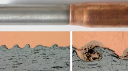
2. As-welded tube-to-tube copper-steel joint.
In addition, for the tube-to-tube specimens, the resistance of the inner tube against the impact of the flyer tube is important. Strength and stiffness (which is directly related to the thickness) must be sufficient to withstand the collision without extensive deformation of the inner tube. Accordingly, in the current example, leak tests have shown that a wall thickness of 3 mm for the internal steel tubes exhibited better leak tightness results than for a wall thickness of 1 and 2 mm.
3. Set-up of the leak test.
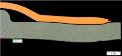
Adding to the leak test, investigations of the interfacial morphology allow more detailed conclusions regarding the weld properties. An example of a metallographic cross section of a welded tube-to-tube specimen with a wall thickness of 3 mm for the internal steel tube is shown in Fig. 4a and b. In the overall view (Fig. 4a), the slight deformation of the inner tube caused by the colliding outer tube can clearly be recognized. The black line at the interface might suggest that no weld was obtained.
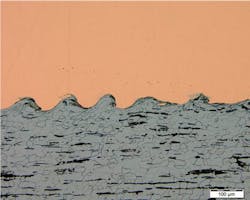
4. (a) The metallographic cross-section of a tube-to-tube specimen with a wall thickness of 3 mm for the internal steel tube; (b) Detail of the wavy bond formation at the copper-steel interface.
However, this can be explained by difficulties in the specimen preparation process of multi-material joints, especially if materials with significant differences in strength and hardness are concerned. In case of copper and steel, material removal will always be slightly more distinct for the softer copper, so that the surface of the copper and steel after polishing are not exactly at the same level. In case of moderate magnifications, the shift in the surface level appears as a dark line, which can easily be misinterpreted as a gap in between the copper flyer and steel target. If, however, higher magnifications are used, the shift in the surface level becomes detectable, because the focus has to be adapted in order to obtain a clear picture of the flyer or target surface. In Fig. 4b, a detail of the weld interface shows that a wavy bond has been formed between the copper and steel.
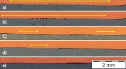
Figure 5 shows different copper-steel weld interfaces resulting from different sets of process parameters—specifically, different values of the stand-off and thickness of the inner tube. The extensions of the arrows indicate the length of the welded zone.
- Gives an impression about a high-quality weld, characterized by a continuous interface with a completely welded zone showing the typical wavy structure. The other examples show weld defects, which might occur if the process parameters are not chosen well.
- Porosities at the center of the welded zone
- Discontinuous interface with a welded zone at the beginning and at the end
- Short welding zones
- No welded interface
In general, the transition from a continuous to a discontinuous weld interface with non-welded zones takes place when the wall thickness of the internal steel tube is too small. Hence, a continuous weld interface with a completely welded zone is usually observed for tube-to-rod specimens and tube-to-tube specimens with a wall thickness of the internal steel tube of 3 mm or more. However, even for tube-to-tube specimens with a much smaller wall thickness of 1 mm of the internal steel tube, welded regions still can be produced.
5. Different copper-steel weld interfaces.
Moreover, a correlation between the weld interface and the stand-off distance has been identified. A comparison of a stand-off distance of 1 and 2 mm shows the tendency of an increasing and more continuous weld length with increasing stand-off distance. However, for some parameter combinations, specimens produced with a large stand-off distance of 2 mm failed catastrophically due to cracks at the weld interface. To get a deeper understanding of this, a more detailed look at the micrographs is necessary.
Figure 6 illustrates different phenomena which can take place at the copper-steel weld interface. The high cooling rate can give rise to shrinkage cracks, while cavitation during melting can give rise to porosities. Intermixing of the materials can occur, resulting in interfacial layers. Under certain conditions, this can give rise to the formation of intermetallic phases. These phases should be limited, as they are likely detrimental to the weld quality due to its brittleness. Below a certain thickness, the intermetallic phases rarely contain defects, and when a wavy interface is present, these intermetallics are formed at the crests of the waves in melt pockets.2 This clearly shows that process parameters must be chosen well to avoid these defects, guarantee a high weld quality, and a robust manufacturing process.
6. Interfacial layers, cracks, and porosities in a copper-steel weld interface.
Copper-to-Aluminum Joints
In addition to the copper-steel joints presented above, also electromagnetic welding of copper (DHP 250) tubes to aluminum (EN AW-6082-T6) rods was regarded in the JOIN’EM project. One test series focused on finding the best parameter set for this material combination. For this purpose, the following parameter variations were considered:
- Copper tube wall thicknesses of 0.9 and 1.3 mm
- Aluminum rod diameters of 21, 22, 23, and 24 mm
- Capacitor discharge energies from 8 up to 21 kJ
- Stand-off distance of 1, 1.5, and 2 mm
- Overlap lengths of 8 and 10 mm
The parameter study suggests that it is important to choose a sufficiently high overlap (e.g., 10 mm), gap width (e.g., 2 mm) and capacitor charging energy (e.g., 20 kJ) to achieve a high weld quality. However, for the set of parameters considered here, the required values leading to the best achievable weld result seem to be independent from the wall thickness. The table lists the optimum process parameters for electromagnetic welding of copper tubes with different wall thicknesses to aluminum rods determined in this study.
The metallographic examination of the welds revealed that at the weld start and at the weld end, the interface is relatively flat, without any visible interfacial layers. At the center of the weld, a wavy interface like that of the copper-steel joints shown above was also observed.
|
Flyer tube wall thickness (mm) |
Energy (kJ) |
Voltage (kV) |
Gap (mm) |
Overlap (mm) |
Free length (mm) |
|
0.9 |
19 |
15.41 |
2 |
10 |
15 |
|
1.3 |
20 |
15.41 |
2 |
10 |
15 |
Overview of optimal input parameters for welding Cu tubes to solid Al rods.
Summary
The study has investigated the weldability of copper tubes to steel and aluminum internal parts by means of electromagnetic welding. The investigation led to the identification of the effects of important parameters of the joining partners (such as wall thickness), the setup (such as stand-off and overlap) and the process (such as capacitor charging energy) on the joining result in terms of leak tightness, weld length, and interfacial morphology of the weld.
Acknowledgements
The presented results were achieved within the project “JOINing of copper to aluminium by ElectroMagnetic fields – JOIN’EM.” This project has received funding from the European Union’s Horizon 2020 research and innovation program under grant agreement No. 677660.
André Cereja is project manager for the European Federation for Welding, Joining and Cutting (EWF). Koen Faes is leader of the Solid-state Welding Research Group, Belgian Welding Institute. Verena Psyk is leader of the Electromagnetic Forming Group, Fraunhofer IWU.
References
1. Kleiner, M.; Chatti, S.; Klaus, A.: Metal forming techniques for lightweight construction. Journal of Materials Processing Technology 177 (2006) 2-7.
2. Psyk, V.; Risch, D.; Kinsey, B L.; Tekkaya, A. E.; Kleiner, M.: Electromagnetic Forming – A Review. Journal of Materials Processing Technology, 211 (2011), pp. 787–829, DOI: 10.1016/j.jmatprotec.2010.12.012.
3. S. Kudiyarasan and S.A. Vendan, “Magnetic Pulse Welding of Two Dissimilar Materials with Various Combinations Adopted in Nuclear Applications,” Indian Journal of Science and Technology, Vol. 8, No. 36, Dec. 2015.
