Why Ice Rinks Choose Carbon Dioxide for Climate Control
Environmentally concerned skaters can rest easy, as more skating rinks turn toward refrigeration systems using coolants with low global warming potentials (GWPs). An average Swedish ice skating rink uses about 1 million kWh of electricity and heat each year, with 40% used by the refrigeration system. For reference, a kitchen refrigerator supporting a 1.02-kW load uses about 9596 kWh a year. Assuming it runs 24/7, 42 kitchen refrigerators would equate to the cooling requirements for a skating rink.
With initiatives to shift away from coolants such as hydrofuorocarbons (HFCs) and other fluorinated gases with high GWP, more skating rinks are using systems optimized for primary coolants like ammonia (R-717) and carbon dioxide (R-744). One ice rink in Sweden installed a 100% carbon dioxide system combined with an optimized heat pump to reduce its energy consumption by 50% to 60%.
While previously applied as the secondary refrigerant, carbon dioxide can be the primary coolant in an optimized heating system to help meet the demands of an ice skating rink’s heating and refrigeration systems. These systems are commonly referred to as second-generation ice rink carbon dioxide systems, since they are being more widely adopted in newly constructed skating rinks.
In addition, systems can be referred to as “direct” if carbon dioxide is used in both the refrigeration loop and circulated rink flow, while indirect systems use carbon dioxide only in the machine room along with a secondary refrigerant. Secondary refrigerants are commonly calcium chloride or glycol, or ammonium hydroxide in Europe.
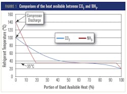
A comparison of ammonia and carbon dioxide as primary fluids in a heat removal system is shows in the graph below. Both fluids exit the compressor and enter the heat recovery system or gas cooler. The comparison is made at a condensing temperature of 35°C for ammonia and a head pressure of 80 bar or 1160 psi for carbon dioxide.
The graph shows carbon dioxide as the better alternative for the rink’s heat recovery system because more heat is available from carbon dioxide at higher temperatures. For example, only 20% of the heat has been removed from ammonia when it reaches 35°C, while the amount of heat removed from carbon dioxide when it reaches 35°C is 60%.
ASHRAE Members can read the full-text PDF here.
About the Author
Leah Scully
Associate Content Producer
Leah Scully is a graduate of The College of New Jersey. She has a BS degree in Biomedical Engineering with a mechanical specialization. Leah is responsible for Machine Design’s news items that cover industry trends, research, and applied science and engineering, along with product galleries. Visit her on Facebook, or view her profile on LinkedIn.

