3 Smart Systems to Improve Lift Operating
Telehandler or boom lift operators have been trained to know the weight and load center of each load they lift. There are cases where, despite following procedure, telehandlers have tipped due to overloading. In addition, operators also risk accidentally misinterpreting the information provided on a load chart. Not only is damage to the telehandler likely, but in extreme cases, the machine’s stability can be affected.
By introducing three key systems, the risk of overloads can be greatly reduced. These systems include automatic attachment recognition, a load management information system (LMIS), and a load stability indicator (LSI). All three work together in the prevention of overloading and damage of telehandlers.
1. Automatic Attachment Recognition
Imagine spending time flipping through a load chart booklet, a booklet that has over 25 attachments listed in it. If the operator accidentally chooses the wrong load chart, the operator can get a false idea of the attachment and machine capabilities. With automatic attachment recognition, that inaccuracy is gone. With automatic attachment recognition, the tag on the attachment and the sensor on the telehandler work together to provide the accuracy needed to deliver the operator with the correct corresponding load chart for the attachment that is fitted to the machine.

The sensor on the telehandler reads the attachment tag, providing the operator with the correct load chart.
Attachments are assigned a unique number and a Radio Frequency IDentification (RFID) tag, which sends radio waves to the RFID transceiver located on the telehandler through a long distance communication system. Once the system has detected the attachment, by using the unique number, it will match the attachment number with the corresponding load chart. To ensure the recognition system has chosen the correct attachment if multiple ones are in the vicinity, the system analyzes the signal strength from each attachment and selects the appropriate load chart.
2. Load Management Information System
A load management information system provides the operator with an indication of how heavy the load is on the machine and where the load is in space. To calculate the load and position on the machine this system combines inputs like:
* Boom angle
* Boom length
* Known machine geometric data.
Forces are calculated by measuring the lift cylinder pressure. Transducers are used to measure the pressure captured in the lift cylinder, which correlates to the amount of load and force on the telehandler boom. Internally, the pressure transducers have a redundant circuitry to ensure integrity of the measurement and to enhance diagnostic capabilities. As both the rod side and the barrel side are being measured, the two sensors complement each other and help provide accurate measurements in all temperature extremes.
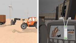
The LMIS and LSI indicators show on the load chart screen for better visibility.
The LMIS system must be calibrated to each attachment. The two calibrations that need to be completed are static and dynamic. Dynamic calibration improves load prediction during boom movement. Once these one-time calibrations are complete, functionality will activate and the production of accurate load predictions will begin.
The main function of LMIS is to provide the necessary data needed to restrict boom movement once the lifted load is about to approach the maximum capacity of the telehandler and attachment. Graphics show the loads exact position on the chart, indicated by a small green circle.

The LMIS indicator shows as a green circle on the load chart screen when the operator is in the desired zone.
The circle moves as the machine does, knowing whether the angle is rising or falling and if the operator is extending or retracting. If the operator moves the load to an area approaching a load chart violation, the green circle will change to either yellow or red, depending on the proximity of the load to the noncompliance area. When moving too far out of the desired zone, the technology shuts down to stop any potential damage or instability to the machine.
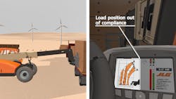
When out of compliance, the LMIS indicator will turn red.
LMIS systems were originally designed for crane applications and are required on telehandlers in parts of Europe and Australia, predominantly when telehandlers are used to pick up suspended loads.
3. Load Stability Indicator
LSI works in conjunction with LMIS. This system consists of a strain gauge sensor mounted on the telehandler’s rear axle that measures slight deflections of the casting as load variations occur. These variations in load provide the system with an indication of the longitudinal stability of the machine as it moves throughout the load chart. Operators will know if LSI is in compliance by looking at its display, which is mounted on the right side of the cabin.

A drawing depicting LSI on the rear axle of a telehandler.
Bonding the LSI sensor the rear axle of the telehandler is a short process that only takes one and a half hours to complete. This step is important, though, because obtaining a good bond between the sensor and axle is key to good system performance and will allow LSI to send signals to the operator when load stability is decreasing.
When load stability is near its limits, the sensors send signals to the control system, which will sound a cabin alarm and prevent functions that further reduce stability from operating. Some of those functions include moving the main telescope out and moving the main lift down. These functions are barred until the load stability increases.
Calibrating the stability system is a straightforward process. By removing all weights and attachments and deploying the outriggers, if available, the operator can begin calibration. Operators will need to calibrate 0 percent load stability (the most stable position) by keeping the telehandler on level ground, and starting with the boom extended. Then with the boom extended and raised off the ground, telescope the boom in. Drop the boom and retract the outriggers, if the telehandler has them.
The next phase is to calibrate 100 percent load stability (the least stable position). To complete this, the operator must extend the boom at a low height and enough weight to lift the rear axle off the ground. Alternatively, the operators may obtain 100 percent load stability by jacking the machine’s frame or lifting it.
While pieces of these technologies have existed in different forms and different regions in the past, some companies have started to adopt them in mainstream telehandler markets. The telehandler industry continues to evolve towards systems that offer operators a greater level of confidence and lower total cost of ownership. For example, JLG Industries, Inc. recently released a system coined SmartLoad Technology, which has implemented these systems collectively. By offering the tech as an all-inclusive package, it has maximized the operator’s confidence while using the vehicle.
Not only will the operator be benefiting from these applications but rental companies will also have peace of mind, knowing the vehicle’s use is staying within its safe operating limits.

About the Author
Phil Holwell
Senior Director of Engineering
Voice Your Opinion!
To join the conversation, and become an exclusive member of Machine Design, create an account today!

Leaders relevant to this article: