Design Essentials: How to Size a Motor Properly to Avoid Oversizing
Download this article in PDF format.
One of the challenges that face motion-control engineers is how to properly select a motor. If the motor is undersized or too small, it will not handle load. If the motor is oversized or too large, the motor will be too expensive in terms of purchase point and operation. Accurately sizing the motor can help prevent either of these scenarios from occurring.
Inertia
One of the primary challenges in motion control is overcoming inertia. Inertia is an object’s tendency to resist changes in acceleration. Overcoming inertia is a constant struggle for engineers, especially on assembly machines that have short motion cycles but require very high speed. A motor needs to supply sufficient force in a linear system, or torque in a rotational system, to change the acceleration of the load in a controlled manner.
The first step in properly sizing a motor is to calculate the load inertia. For example, a rotating mass’ moment of inertia (J) can be determined by:

This describes the moment of inertia for a point mass (m) at specific distance (r) from the rotation axis. The formula can be used to build up moment of inertia for complex shapes like cylinders, disks, spheres, and blocks. Load inertia is reflected back to the motor shaft from the load and the components in between. The value should include any extra mechanical elements that motor is responsible for moving. This could mean parts such as screws, pulleys, belts, or couplings. These additional moving parts will demand higher performance from the system.
Finding the appropriate analytical expression for complex systems depends on the weight, factoring in acceleration due to gravity, rather than just the mass of the parts. The motor-sizing process requires the total system inertia, including both the load inertia and the motor inertia. The tendency of many engineers is to only calculate the actual load and gearbox into the inertia while leaving out the weight and inertia of the belts, pulleys, and other mechanical components.
This method is why many adapt the 10% oversize approach and bump up their motor requirements to the next major size, or use the same frame size with a large torque value. Consequently, it leads to oversizing the motor.
The ratio of load inertia to motor inertia indicates how effectively the motor can control the load. When the inertia ratio is high, it indicates that the system may have a hard time controlling the load. A low inertia ratio obviously indicates the opposite; the motor will have an easier time and be more effective controlling the load. However, a low inertia ratio could mean the motor is oversized for the system, costing more and being larger than necessary.
Ultimately, the rule of thumb is based on performance. Inertia mismatches in servo and motion control can occur as high as 60:1, but the performance can be excellent depending on how well you can tune the system. Auto-tuning drives can compensate for machine resources and vibration to support accurate performance at even high speeds.
Torsional flex or compliance is an important factor in motor sizing. A motor sized at a 1:1 inertia ratio may have problems controlling a load if the system is too loose and has a high compliance. The system could require tightening or the operation parameters may need to be relaxed.
Gearboxes help manage inertia by reducing it via the square of the gear ratio. Gearboxes also cut motor speed, which can be problematic with stepper motors as they typically only run at several hundred revolutions per minute (RPM). Servo motors benefit from the use of gearboxes because they operate at higher speeds—between 2,000 and 6,000 RPM.
Application Requirements
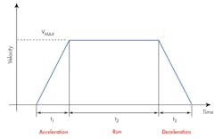
The trapezoidal motion profile shows the acceleration and deceleration areas along with the constant velocity range. (Courtesy of Motion Control & Motor Association)
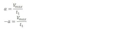
After determining the inertia for the system, the next step is to determine the operating parameters and torque required. One should start by defining the motion profile for the load. The most basic form is a trapezoidal shape; a burst of sudden acceleration that’s followed by a period of constant velocity and ending in a deceleration. Acceleration and deceleration can be determined by:

Looking at the simple motion profile above, the acceleration and deceleration mirror each other and can be determined by:
Torque Requirements
Once you have the load inertia, acceleration, and deceleration, you can calculate the amount of torque required to position the load. The total torque (Tt) is the sum of the acceleration torque (Tacc) and the load torque (TL). The load torque is the sum of mechanical losses in the system, which is typically loss due to friction and gravity.
To calculate the friction, one multiplies the friction coefficient for the sliding surface and the normal force to said surface. Friction is a design factor that can be easily forgotten in the motor-sizing process. It is helpful in determining the frictional force for a measuring instrument such as a torque wrench.
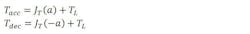
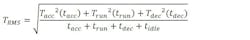
The root-mean-square (RMS) torque is the torque required from the motor for the application. It considers not only the amount of torque, but also the duration of the torque. To determine TRMS, the torque acceleration and torque deceleration must be calculated:
The last torque value for the equation is the run torque. This is the torque value that maintained constant velocity throughout the run phase and the small span of idle time at the end of the move.
Once you have the TRMS, you can determine the required speeds by referencing speed-torque curves. Manufacturers provide these curves for their motors that describe their performance during operating speed ranges. These data plots are an essential reference to determine if the motor is appropriate for the application conditions.
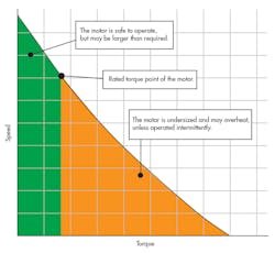
The speed-torque curve shows the rated torque point of the motor. The low end of the curve is where the motor is safe to operate, but may be oversized (green area). On the high end of the curve, the motor would be undersized and can possibly fail overtime (orange area). (Courtesy of Motion Control & Motor Association)
Infrastructure and Environment
During the sizing process, external conditions must be accounted for when choosing the right motor. One must consider the voltage and frequency characteristics of the power source. The motor you select may vary depending on the power available.
The operating environment also is crucial. Will the motor be exposed to harsh environments such as low temperatures or increased moisture environments? Will it be placed in a remote location making regular maintenance visits difficult? Is the motor needed for wash-down environments? The answers to these questions will have an impact on what motor you choose.
Physical Motor Aspects
An easy way to control the load is to increase motor power. However, physical limitations may prevent you from bumping up the motor size. Space restrictions restrict the frame size and length of the motor. Some manufacturers increase motor power by stacking magnet laminations while maintaining the same frame size. This makes the motor longer but does not increase width. However, this could suffer from space restriction as well.
When it comes to stepper motors, oversizing is common practice. Stepper motors are designed with high pole counts—on the order of 50 or more. They can be commanded to advance in discrete steps rather than in continuous motion and are able to operate in open-loop, making them effective and inexpensive.
Many will oversize stepper motors to prevent them from stalling when placed in over-torque mode. There’s typically no feedback-monitoring device on the motor shaft, so the motor stalls without being noticed. By properly sizing the motor, one can run stepper motors in closed-loop allowance. This helps saves money, which can be invested into purchasing an encoder.
Beyond the Basics
Engineers can apply several techniques to shrink the size and cost of a motor. The first is to add a gear reducer. The gearbox may reduce motor requirements. A worm gearbox is about 30% efficient, while a planetary gearbox is 85% efficient. Using a high-efficiency gearbox can reduce the load on the motor.
One can also consider replacing servo motors with stepper motors. After calculating the required torque, a stepper motor can be used in low-speed applications. With the right frame size, a stepper motor can work on its own without the need for a gearbox, providing significant cost savings.
When choosing a motor, a common mistake is to opt for a motor with continuous duty torque, which is equal to the max torque requirement. Motors have two modes: continuous duty mode/peak or overload mode. The motor can operate at peak torque/current for brief intervals without harming the motor windings. Many applications consist of brief and rapid moves.
Choosing a motor at max torque requirement means overpaying for the motor. When properly sized, one can select a motor that’s able to operate in the overload torque range for brief periods of time. This allows users to select a small motor and save money.
When selecting a motor using this method, pay close attention to duty cycle. The intervals of peak current should be short so as stay under specifications, and occur at a low-enough frequency to enable the motor windings and electronics to cool off. Duty cycle from the standpoint of the gearing is important to prevent premature wear and failure.

