Linear Bearings: Understanding the 2:1 Ratio and How to Overcome the Stick-Slip Phenomenon

Back in the 1980s, Pacific Bearing Co. (PBC) invented and commercialized plain bearings, which were sized to be interchangeable with linear ball bearings.
Plain bearings worked very well in certain applications—mainly those in environments that were hot, cold, or dirty, or included high vibrations, high static loads, or non-lubricated and short strokes less than twice the bearing’s length. These were just the sort of applications in which recirculating ball bearings failed miserably.
But plain bearings were quickly found to be unacceptable replacements in applications requiring low coefficients of friction, high speeds, or high moment loads. In fact, some applications with high moment loads caused plain bearings to simply bind up; all motion would cease or become jerky (also known as stick-slip motion). Early on, the assumption was that plain bearings could not handle the same moment loads as equivalently sized recirculating ball bearings.
What engineers failed to realize was that there is a geometric relationship that describe the allowable working space of plain bearings. This went unrecognized until PBC published the Binding Ratio (aka, 2:1 Ratio) in the 1990s. Two decades later, some engineers still don’t realize the scope of this rule and that it applies to all linear motion systems, not just plain bearings. They also don’t know that the Binding Ratio isn’t always 2:1. It varies with the application and can be larger or smaller than 2:1.
The Binding Ratio
The “Binding Ratio” is defined as the maximum ratio of moment-arm distance to bearing length that will not bind (prevent motion). It is often displayed numerically as X:Y, where X is the moment-arm distance and Y is bearing length. Typically, X is divided by Y so that the ratio can be expressed as X∕Y:1. It is commonly simplified to 2:1.
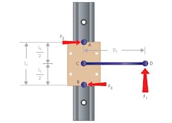
One of the key principles behind the Binding Ratio is Sir Isaac Newton’s Third Law of Motion: For every action there is an equal and opposite reaction. Applying a force, F1, on a bearing at some distance (D1) from the center of the bearing, creates a moment force. To resist that moment, two resulting forces, F2 and F3, are created at each end of the bearing. Multiplying these two forces by the coefficient of friction, μ, creates a drag force.
At some point, the drag force will surpass the drive force and motion will cease. The size of the drive force is irrelevant, as the maximum moment arm (as a ratio to bearing length) is limited solely by μ. Here are the derivations and proofs of this concept for two different situations.
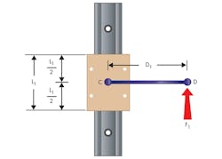
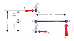
In this example, there is a single applied force, F1, applied to a linear bearing at a known distance, D1. Assuming the bearing and moment arm are a rigid body, they move in the direction of F1. It can also be assumed that linear bearings allow only one degree of freedom, the axis of motion.
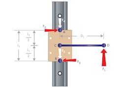
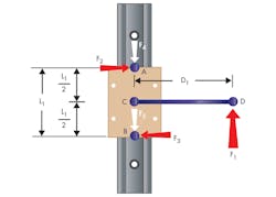
Building on the First Law of Motion (an object at rest will stay at rest until the vectored sum of all forces acting upon it is greater than zero), the carriage accelerates only if F1 exceeds the sum of the drag forces, F4 and F5. In practice, there is an additional drag force due to the weight of the carriage and its payload. For now, this additional resistance will be disregarded.

To begin the statics equations, point C is chosen as the fulcrum and all forces and moments are summed around this point.
Linear bearing systems are designed to be rotationally stable, so the sum of the moments about point C equals zero (Eq. 5). Equations 6 through 10 (below) simplify this equation to solve for the resulting forces F2 and F3.
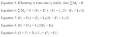
At the transition point, where the bearing goes from binding to motion (or vice-versa), the acceleration value from Eq. 4 goes from a negative to a positive value. To solve for this, set the value to zero to find the specific transition point. The following group of equations is valid only at the transition point, where acceleration equals zero.
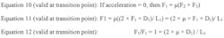
For an application to move, the driving force must exceed the sum of the drag forces. Equation 12 shows there is a relationship between μ, bearing distance, and moment arm distance. Rearranging Eq. 12 derives the three conditions that must be met for an application to move.
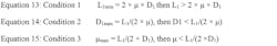
Equations 13 through 15 separate the maximum allowable μ, the maximum allowable D1, and the minimum allowable L1.
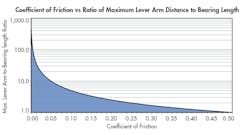
To illustrate that the Binding Ratio is a pure derivative of μ and the relationship of the bearing length to moment arm distance point, the graph above shows the maximum allowable Binding Ratio for any coefficient of friction. It demonstrates that the smaller μ is, the larger the Binding Ratio can be. For this graph, Eq. 14 was used and L1 was set to a value of 1. The X-axis shows different values for μ, and the Y-axis shows the Binding Ratio. For illustrative purposes, the lowest common μ in linear motion systems is in recirculating-ball type linear guides where µ can be as low as 0.001.
Using Eq. 14 and setting the L1 to 1, the result is a Binding Ratio of 500:1. The highest μ, 0.5, is found in modern-day plain bearings. However, most materials have a µ ranging from 0.1 to 0.25. The graph also illustrates the importance of a low μ for applications with a high moment load and a large moment arm distance.
The assumption was made that all forces are applied in an axis parallel to the direction of travel.
This eliminates the complication and redundancy of vector mathematics. In most practical applications, the force would actually be applied at some non-parallel angle which would require the force to broken down into its X- Axis, Y-Axis and Z-Axis vectors. The end result would be the same as shown here. The only difference is that the equations would have to be repeated three times, once for each axis.
Understanding Stick-Slip
One of the most frustrating and potentially devastating problems an engineer can face is stick-slip motion. It is particularly devastating because it can bring production to a standstill until the problem is solved. Until now, we have treated µ as a single value. In reality, every material has two coefficients of friction: static (µs) and dynamic (µk). In general, µs is greater than or equal to µk.
Using Machinery’s Handbook as a reference, a basic comparison of materials shows that, on average, µk equals to 65% of µs . This value will certainly be different for every material, so be sure to check a material’s specific value for µs and µk.
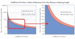
Knowing that the greater µ is, the lower the Binding Ratio will be, the difference between the static and dynamic coefficient of friction means that there could possibly be some designs which will work when the system is already moving, but will not work when the system is at rest. The plots above show the Binding Ratio for different static and dynamic coefficients of friction. The graph on the left is a close-up the one on the right. Two curves are plotted in each graph. The top curve represents the Binding Ratio curve based on µs. The bottom curve represents the Binding Ratio for µk based on the assumption that µk is 35% less than µs.
The blue area at the bottom of the plot is the “free motion zone” where motion will not theoretically be interrupted by binding due to the Binding Ratio. The red area is the area between the curves of the Binding Ratio for µs and µk. The white area above the curves is the “no motion” zone where it is likely that motion will not occur. It is the claim of this author that stick-slip is more likely to occur for applications where the Binding Ratio is in the red zone (the area between the curves).
These graphs are not meant to be used as engineering reference charts, but for illustrative purposes only. Values for the X-axis of both graphs have been removed to prevent accidental misuse. Instead, these images should be used to illustrate the point that all bearing systems have two different coefficients of friction (static and dynamic) and therefore, they also have two different Binding Ratios.
Linear recirculating-ball bearings often have static and dynamic coefficients of friction which are almost identical, so there is little change in the binding ratio. With plain bearings, there is typically a larger difference between the static and dynamic coefficient of friction, so there will be a larger variance in the binding ratios.
Stick-slip is often described as a temporary cycle of alternating rest and motion. Some systems experience stick-slip motion only at certain locations in the cycle. If this type of motion is repeatedly observed at the same location, it is likely that an unknown force acts on the system there. The most common external forces are caused by misaligned linear rails, dimensional change in the rails, or an imperfection in the rail, which can also be caused by damage.
These additional forces are not accounted for in any of all of equations presented here. These forces must be multiplied by the force of friction and added to the resultant forces from the moment load. Looking back to Eq. 10, above, it can be rewritten as Eq. 16 (below) to account for these additional forces. Provided that the applied force, F1, is still larger than the frictional forces, then there will still be motion. However, if the sum of frictional forces exceeds the applied force, there will be binding.

Because the system was likely in motion before these additional frictional forces were applied, the momentum of the system will help push through the momentary zone where these external forces are applied. As the system moves through this zone, the applied force will re-engage to cause a short burst of motion before causing binding again. The momentum will again help push the system through the binding where the cycle can repeat. This is stick-slip in its simplest form.
Complications and Limitations
By far, the largest complication of working with the Binding Ratio is that the actual µ is hard to quantify and may change based on environmental circumstances. To further complicate matters, some manufacturers either do not list µ in their product literature or may only list µk to make their products look better. Another issue with accurately using the Binding Ratio is the additional unaccounted and often unpredictable forces caused by misalignment. In addition, with respect to some more advanced bearing materials, such as PBC’s Frelon Gold, µ will actually change based on the load applied. A good rule of thumb is to take the expected µ and double it. This ensures the design will have an adequate safety factor.
Another complication results from using the incorrect bearing length. Aside from mathematical and unit conversion errors, the most common problems result from using the wrong bearing length in formulas shown earlier in this article. This is easy to do because bearing length is not the overall bearing length, which is a common and understandable assumption. Instead, bearing length is defined as the length of the bearing carrying the load. In a ball bearing, this is typically called the “load zone.” Few manufacturers publish specifications on their products’ load zones, so engineers have to guesstimate a specific bearing’s (“load zone”) length. Another common mistake happens in applications with several bearings on a single shaft. The correct bearing length is the center-to-center distance between bearings, not the overall length (outside edge-to-outside edge distance).
Troubleshooting Stick-Slip
There are several steps engineers can take to stop or prevent binding and stick-slip. This article is not intended to be an all-inclusive troubleshooting guide but it will list a few practical ideas which based on the theoretical principles previously discussed. There are five very simple concepts which, if implemented, should solve a binding/stick-slip problem for most applications. The five simple concepts are, in no particular order:
• Reduce moment arm distance.
• Increase bearing length.
• Add a counterbalance.
• Remove external forces.
• Reduce bearing friction.
The most logical way to prevent binding would be to reduce the moment arm distance. This will move the application out of the binding or stick-slip zone and into the smooth motion zone (Figs. 7 and 8). Although this might seem like a great idea, it is simply not an option for most applications, as other constraints limit this distance.
The next suggested change would be to increase the bearing length. This can be done by switching to a longer bearing or carriage, increasing the spacing between several bearings or adding a second bearing to a single bearing system. This may work for many applications; however, not all systems can handle longer bearings.
In this case, the next suggestion would be to try to add a counterbalance to reduce the moment and, in turn, reduce the resulting forces and frictional forces (Fig. 5). Again, this may not work for all applications as there may not be space to add a counterweight or overall system constraints prevent the additional weight or cost of the counterweight.
A different solution would be to remove external forces. These are most often the result of misalignment or a damaged shaft or rail. Damaged shafts and rails may or may not be repairable. They may have to be replaced to eliminate the additional forces. And fixing a misaligned a set of rails often adds considerable time and expense to the assembly process. It may work for a low-quantity build, but is often unacceptable for mass production, which renders this option impractical for many applications.
The final solution would be to reduce the bearing friction. There are two primary ways to do this: add or change the lubrication to reduce the coefficient of friction, or change the bearings to a different style with a lower coefficient of friction.
Some applications experience smooth motion in one direction and binding in the other direction. This is almost always caused by forces previously unaccounted for. Typically, forces are accounted for in one axis, but forces are seldom applied in only one axis. It only takes one axis with a force applied at a distance farther than the Binding Ratio distance to have the whole system experience stick-slip or complete binding.
Troubleshooting this issue can be especially frustrating, as the system seems to work half of the time. In this case, the most common solution is to increase the bearing length either by increasing the distance between bearings or switching to an extended-length bearing.
Jonathan R. Schroeder is Engineering & Product Development Manager at PBC Linear.

About the Author
Jonathan R. Schroeder
Engineering & Product Development Manager
Voice Your Opinion!
To join the conversation, and become an exclusive member of Machine Design, create an account today!

Leaders relevant to this article: