Mobile manipulators go mainstream
One of the hottest topics in robotics today is that of mobile manipulators. These are robot systems consisting of a robotic manipulator arm mounted on a mobile platform. Such systems are particularly of interest for space exploration, military operations, home care, and health care. One reason the topic is becoming more interesting is that the technologies necessary to implement mobile manipulators (mobile platforms, robot manipulators, vision and tooling) are largely available off the shelf.
The same can be said for much of the software it takes to run these robots. It is interesting to see how roboticists can design and test mobile manipulator designs in a physics-based simulator and then seamlessly implement the design in real-world systems. It’s possible to use a single software architecture for both simulation and implementation. This advances the design cycle and helps promote innovative robotics research.
We can consider the KUKA youBot as an example. The KUKA youBot is a small, versatile machine designed for research and education in professional service robots. The engineering team at KUKA had numerous challenges in designing the youBot. Among other things, they went through several design iterations to ensure the drive motors provide enough torque at the base to carry the payload. The drive electronics also had to deliver sufficient motor current for performing pick-and-place tasks with the manipulator.
The KUKA youBot is an open platform on its way to becoming a reference platform for hardware and software development in mobile manipulation. Because it is an open platform, there are numerous APIs available to connect it with various software packages. In particular, there are APIs that let the National Instruments, Austin, LabVIEW software work with youBot. LabVIEW (short for Laboratory Virtual Instrument Engineering Workbench) is a system-design platform and graphical development environment. LabVIEW is commonly used for data acquisition, instrument control, and industrial automation on a variety of platforms. The LabVIEW Robotics Module was designed specifically for robotics applications.
During the development of LabVIEW KUKA youBot APIs, software engineers relied heavily on simulation to design and build steering and kinematics functions prior to testing on the physical robot. The LabVIEW Robotics Simulator uses freely available software called the Open Dynamics Engine. This is a physics-based simulator used to emulate robotics designs. Custom 3D CAD model designs can be imported into this simulator from CAD software such as SolidWorks and Google Sketchup.
With the CAD model imported into this environment, users define individual joints in the robot as to their type. The robotics simulator characterizes the physical dynamics of individual components and creates the dynamic model of the entire robotic system. Rather than forcing users to solve differential equations, the robotics simulator creates a physics model of the robot.
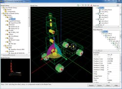
Developers can use a Robotics Model Builder Wizard, a component of the LabVIEW Robotics Simulator, to build a custom youBot simulation environment. Ideally the same algorithm code developed in a simulation environment can execute on the actual robot or in a simulated state with the only change being the specified target. This provides the benefits of rapid prototyping and validation in simulation without sacrificing time to translate the algorithm to run with hardware.
The LabVIEW Robotics Module introduces a hardware abstraction layer to address the issues of controlling algorithms and validating code in simulation. Each I/O software interface includes a general implementation, which could take the form of a simulated or physical device. This makes it possible for engineers to test algorithms such as mapping, steering, and path planning in simulation before using the same code on physical hardware.
Control regimes
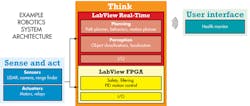
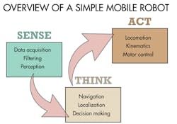
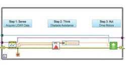
Just as software used in robotic work has become more standardized, so, too, have the control regimes used for managing robot actions. For example, many robotics-system architectures can be divided into three main parts: sensing, thinking, and acting. Sensing typically involves reading sensor data. Mobile robots typically are outfitted with sensors, such as ultrasonic sensors and LIDAR (Light Detection and Ranging) sensors, that help find obstacles or orient them with regard to their position in an environment. Thinking functions are those that use sensor data to plan robot movements. For mobile robots, path planning and obstacle avoidance algorithms are usually part of this scheme. The “act” portion of the control regime translates the positioning commands into drive signals for specific actuators.
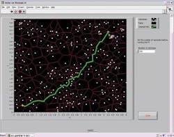
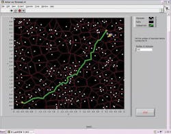
There are software drivers widely available for many of the sensors that find frequent use in mobile robots. Robotics has progressed to the point where path planning and obstacle-avoidance techniques are widely available as well. For example, in the case of LabVIEW software, standard software drivers can work with LIDAR sensors to acquire range data and pass it to advanced mapping and navigation algorithms. There are many path-planning algorithms in common use today. One such algorithm, called a Voronoi algorithm, notes the position of obstacles and computes the possible paths around them. When the robot is given a starting and ending point, the LabVIEW Voronoi VI computes the shortest path from the start to the goal.
One problem with path-planning techniques is that they can only take into consideration the obstacles they know about ahead of time. So robot designers frequently augment their control strategies with obstacle avoidance routines. These routines take over when, during travel, sensors note a conflict with the planned path.
As with path planning, there are many algorithms available to modify a path based on real-time sensor data. Several of these are available as VIs for LabVIEW software. One in this category is the vector-field histogram technique. The VFH creates a so-called histogram grid as a statistical representation of the robot’s environment. Basically, it constructs a 2D histogram grid in real time using the robot’s range sensor data. It then checks consecutive sectors in the grid to find an area registering an obstacle density below some threshold; finally, it selects a path around the obstacle that comes closest to the target direction.
Inside the youBotThe KUKA youBot base uses an omnidirectional drive system with mecanum wheels. Unlike standard wheels, mecanum wheels consist of a series of rollers mounted at a 45° angle. This lets the robot move in any direction, including sideways, which facilitates maneuvering in tight areas. The KUKA youBot has an onboard computer and can also be controlled by NI CompactRIO systems. Connected to the base of the youBot is a 5 degree-of-freedom arm. The arm is a five-link serial kinematic chain with all revolute joints. A relative encoder gauges the rotation of each joint in the youBot. The youBot’s wrist is equipped with a two-finger parallel gripper with a 2.3-cm stroke. There are multiple mounting points for the gripper fingers that users can choose based on the size of the objects to pick up. The youBot can be controlled via LabVIEW or ROS (Robot Operating System), an open-source software framework for robotic development. |
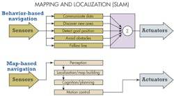
Of course, sometimes robots don’t know much about their surroundings ahead of time. Autonomous robots must be able to generate a map of their environment on the fly using their sensor information to determine where they are. The term used for such scenarios is simultaneous localization and mapping, or SLAM. SLAM routines are especially challenging. They usually involve combining mapping techniques with ad hoc schemes using sensors to react to the state of the environment.
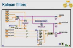
Kalman filters may be used in such situations to help manage the information coming from a large number of sensors. The Kalman filter algorithm uses a series of measurements over time and uses them to estimate unknown variables. The algorithm is usually formatted in two steps. First it estimates the current state variables, along with their uncertainties. It updates these estimates every time it takes a new measurement using a weighted average or previous measurements, with more weight given to estimates with higher certainty. The algorithm’s recursive nature lets it run in real time using only the present input measurements and the previously calculated state.
In robot navigation, Kalman filtering is sometimes used as an aid in analyzing sensor data to discern features, lines, trees, doors, and so forth. Given a set of possible features, the Kalman filter might be used to estimate how closely a feature matches an object in the map the robot knows about.
Fortunately, developers need not create Kalman filtering algorithms or other SLAM-type routines from scratch. Modern robot-development software generally provides these and other commonly used routines from libraries.
All in all, robotic projects tend to be more iterative than others because the code associated with handling the actuators involved tends to need fine-tuning and tweaking. But today developers can make use of libraries for widely deployed routines deployed in path planning inverse kinematics, obstacle avoidance, and kinematics for robot arms. It’s best to use these libraries as a starting point whenever possible to help minimize development effort.
This file type includes high resolution graphics and schematics when applicable.
Resources
KUKA youBot store, National Instruments Corp. (robotics page), Open Dynamics Engine
