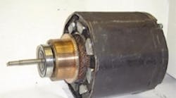
In the 1970s, the big question in motion system design was whether to employ hydraulic or electric actuation. Today, in the era of electronic motion control, the question is wheter to use brush or brushless motors.
All electromagnetic motors, regardless of construction, operate on the same principle. Whether brush or brushless, they produce torque through the interaction of two magnetic forces: the "field" and the armature. In permanent- magnet motors – because the field force is generated by magnets – the controlling electronics need only regulate the electromagnetic field in the armature.
If everything in a motor is lined up right, putting current in the armature produces torque. However, once the motor starts to turn, everything isn't lined up anymore. After the motor moves, you have to change the current in the armature to keep it moving. Switching the current as the motor rotates is called "commutation."
Permanent-magnet dc brush motors achieve commutation by mechanical means. As the motor rotates, brushes slide along a commutator bar, connecting different sets of armature windings at different motor positions. Because commutation is inherent in the motion, dc brush motors are relatively easy to control. But the simplicity is offset by a number of problems.
Some of the drawbacks are due to the brushes themselves. Brushes arr under heavy current load, producing electrical noise. They also wear, casting off carbon dust in the process, and must be replaced regularly.
Another concern relates to the rotors. Rotors on brus motors are made of copper wire wond on a steel core. Not only do they possess a lot of inertia, they tend to be longer than normal, extended (with the motor) to allow for the commutator assembly. Because of their size, brush-type rotors often lack the agility to move the light inertias common in servo applications.
Size is also limited by temperature considerations. Because the windings rotate inside the stator, they can be difficult to keep cool. This usually means that the rotor must be enlarged further, at the expense of response, to accommodate fatter wire which generates less heat.
Brushless dc motors, as their name implies, operate without brushes. Instead of mechanical commutation, they rely on electronic commutation – where solid-state switches keep winding currents in synch with the rotor. As a result, the controller must be able to sense the position of the motor to generate torque.
One way to do this is to approximate position using a few, inexpensive sensors. The method, called "six-step commutation," is a little bumpy, but it works. A more sophisticated method, based on feedback from an optical encoder or other such device, is called "sine wave commutation." Here, the controller regulates motor current with great resolution, keeping output torque smooth and precise.
One advantage for brushless motors is thier small size. Brush motors are considerably larger for several reasons.
First, eliminating the commutator assembly saves space. Second, the windings in a brushless motor are on the outside firmly bonded to the frame, allowing direct cooling. Third, brush motors give up efficiency because of the power lost in brush voltage drop and brush friction. Brushless motors also have less rotor inertia because the rotating magnet assembly is lighter than the armature of a brush motor.
Brush-type motors have some advantages too. Brushless motors require more power devices and more wiring. And because of their controllers, they're more expensive to implement, especially in the lower power ratings where the control accounts for a larger portion of system cost. Sometimes brushless motors do not produce torque as smoothly as do brush motors, mainly because the offset error common in current sensors causes torque ripple.
All the right moves
One application area that magnifies the difference between brush and brushless motors is high acceleration. Assume that a load inertia of 1.4 × 10⁻⁴ kg-m2 must be accelerated from 0 to 3,000 rpm then back in 20 msec. Because the motor must accelerate the load as well itself, the more motor inertia, the more torque.
Using standard (Kollmorgen) motors, the best brush motor for the job (TT-2933) has a rotor inertia of 0.0014 kg-m2 and a peak torque output of 7 Nm. The most well-suited brushless motor (B-102-A) has a rotor inertia of just 0.00003 kg-m2 and a peak torque of 1.4 Nm, about 20% of the brush motor torque.
To accurately compare both approaches, you can run a simulation using the ModelQ software package, available at no charge. After installation select the September model from the combo-box at top center and click "Run".
The model you'll be looking at shows the time to accelerate the motor to vMax rpm using the peak torque of both the brush (tPeakB) and brushless (tPeakBL) motors. The inertias of the brush (jB) and brushless (jBL) motors must be considered along with the load inertia (jL).
Notice that as the load inertia (jL) increases, it favors the larger brush motor. But when the inertia falls below 0.0003 kg-m2, the smaller brushless motor can outperform its brush equivalent using just 1/5 the brush motor's torque.
In the bag
An example of a motion system that demands high acceleration can be found in a bag cutter. Such machines have no time to waste as material spools off a roll. In repetitive fashion, the motor driving the knife must quickly accelerate the blade to full speed, then retract just as rapidly.
The lighter rotor inertia of a brushless motor could prove to be a significant advantage because it reduces the amount of work required to move the blade. Also favoring a brushless solution is the fact that brush wear increases in high acceleration applications.


