How to program SoCs for stepper motors
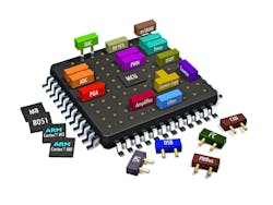
It’s increasingly common for designers to pair stepper motors with motion-control SoCs. In fact, more design engineers than ever are setting up SoCs themselves for motion applications. These chips differ from other options in that they are compact mixed-signal devices that incorporate circuits for analog signals, digital signals, sensors, and even lights and micromachines with mechanical functions.
Stepper motors offer benefits of their own. They operate open loop, which makes stepper designs simple and economical. Many position with accuracy of 3 to 5% of a step, and errors don’t accumulate from one step to the next. Stepper output speed is proportional to the frequency of input pulses, so myriad rotational speeds are possible.
Measure sensor input
Assume we’re designing two pointer gages in a vehicle dashboard for a speedometer and a fuel meter. Sensors track vehicle speed, wheel speed, and fuel level and give out electrical signals based on voltage, current, or frequency and proportional to the levels of measured parameters. Here, we can use two stepper-motor designs consisting of a stepper motor, the specific gage’s sensor, and a SoC microcontroller. Through the sensors, the SoC tracks voltage, current, or frequency. The signals then go through filters to controls and spur motor response.
Voltage input goes through an analog-to-digital (a/d) converter in the SoC, but a/d converter output tends to be noisy. Therefore, a software-based filter called an infinite impulse response (IIR) filter cleans the signal by averaging signals over time. Another problem is a/d converter offset error, which is a small and consistent voltage that shifts the digital signal off the analog. Here, most designs ground a/d converter input and track the digital value to determine offset. Then the SoC subtracts the offset from the converter output. A third problem is potential mismatch between sensor output and a/d converter input range, which degrades resolution. Here, it’s helpful to use a newer SoC. Many today are programmable. That lets users scale the sensor output-voltage range to that of the a/d converter input range.
Current input measurements are similar to voltage input measurements. Here, it’s prudent to connect a resistor of the appropriate value to the a/d converter input so the SoC can change input current to a voltage and measure it with the a/d converter.
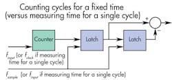
Frequency input is measured in one of two ways. The common approach is to count frequency cycles for a set period of time. The counter fixes on sample rate, fsample, and increments at every cycle of input signal finput. This generates output at the constant fsample rate. Another approach is to measure the time it takes to complete a single cycle. Here, the counter continuously increments at clock frequency fclock and fixes on input signal finput, so this scheme updates at the rate of the input frequency finput.
Both methods for measuring frequency have distinct advantages. Counting cycles is best for measuring higher frequencies. Measuring a cycle period is better for lower frequencies. However, using one technique only gets decent resolution (with small relative error) over limited input frequency ranges for a given clock or sample frequency. Another option is to support multiple ranges — that is, several selectable clocks or sample frequencies. This requires programming on the SoC to determine when it is best to change the range or measurement method. Yet another option is to use a hybrid method to measure the width of all the cycles that can fit into a specified sample period.
Process measured data
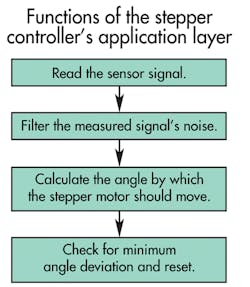
Now assume we’re using a SoC-driven stepper motor for a general rotary-positioning application. After measuring sensor input, we calculate the angle by which the SoC should drive the stepper motor. Two factors largely dictate this value.
- The minimum deviation check. When the difference between a newly commanded angle and the present angle exceeds a certain threshold, the SoC drives the stepper motor to eliminate the difference between the two. Threshold prevents smaller differences between the angles (due to noise or calculation roundoff errors) from rotating the motor
- The relationship between angle and input signal. Here, designers calculate the range of input signals that the application will generate as well as the range of positions that the stepper must output. Interpolation can then predict the output position for specific inputs.
Drive for smooth output
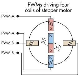
SoCs can drive stepper motors in several ways. Consider a motor with a two-pole permanent-magnet rotor. One full step corresponds to a mechanical angle of 90° so such motors are usually microstepped. The SoC applies cos/sin analog current signals to the coils either by double pulse-width modulation (PWM) or through a digital-to-analog converter. Motor-rotor flux linkage is the same for any rotor angle thanks to the set mechanical construction of the motor, so torque is constant.
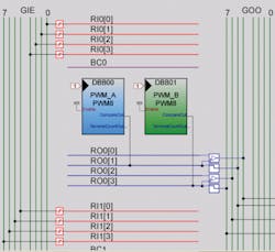
Within the SoC is a PWM drive and timer. Typically, four different PWM signals of appropriate duty cycle (as the percentage of time that voltage pulses excite coils) and frequency drive the two-pole motor’s four coils. But SoCs that apply just two PWM signals get the same output performance. Proportional currents defined by sine and cosine functions go through the two windings.
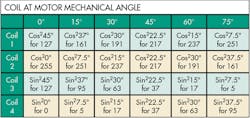
Let’s divide each of our motor’s 90° mechanical steps into six microsteps driven by 8-bit PWMs. Assume we have a lookup table in the SoC firmware to drive the different coils of the stepper motor. Within the programming, the lookup table has an array of compare values that replaces runtime computations and gives values of the PWMs that represent duty cycles scaled to 255 (for the 28 – 1 bits):127, 161, 191, 217, 237, 251
255, 251, 237, 217, 191, 161
127, 95, 63, 37, 17, 5
0, 5, 17, 37, 63, 95
How did we get these values? Well, the motor can turn 360° and each full step corresponds to 90° divided into six 15° microsteps. There are 24 microsteps in total for one full motor rotation so each value (when multiplied by 255) gives set duty-cycle bit values.
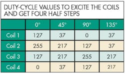
Now calculate the full, half, and microsteps using the lookup table. We get full 90° steps by driving coils 1 to 4 with PWM values 127, 255, 127, and 0, respectively.To get half steps, two consecutive coils must have the same electric strength. That means for our example the SoC drives them with PWMs of duty cycles of 217 each and the opposite coils with 37 so that the stator stands in the middle of the two coils. Duty-cycle values to excite the coils and get Four half steps are also set.
To get microsteps, we drive corresponding sine and cosine values to the coils so the stator advances through positions between coils. Each microstep is 15° and we get one full step using six microsteps.Response time determines the rate of duty-cycle updates which, in turn, dictates the speed at which the motor rotates. A timer (in a signal-triggered program called an interrupt service routine or ISR) controls the update rate of the PWM duty cycle. Timer interrupts come at intervals equal to the response time divided by the total number of motor steps.
The above examples only show how to drive stepper motors with single modes of stepping. Drawbacks of sticking to only full and half steps are that they can cause jerky motor movement, poor resolution, and slip. Likewise, microstepping can exhibit either slow response or jitter if run under a high update rate to get faster response.
The solution is to combine step modes to tailor motor output to application demands. For example, stepper motors must output sufficient torque before they can move loads with full stepping. To reach that torque, we start a motor using micro and half steps. Then we switch to full stepping. The same is applicable when a stepper motor must stop. High running speed under full stepping usually prevents motors from coming to a quick halt, but microsteps at the end of the movement can stop the motor at the correct location.
Note that we can’t universally apply this combination of stepping schemes. Other schemes are more appropriate in select applications.
Stepping with only microsteps is acceptable when the application requires only small moves over short distances.
Stepping with micro and half steps is useful when the application needs a trapezoidal speed profile with a period of acceleration followed by a period of constant speed and then a deceleration to stop. More specifically, this mode of driving is suitable when the number of steps is greater than twice the number of minimum microsteps required to accelerate. The motor accelerates under microstepping; runs at constant speed under half steps, and then decelerates under microstepping.
Stepping with micro, half, and full steps is appropriate when the number of steps is greater than twice the minimum combined number (microsteps plus half steps) required to accelerate. Here, the motor starts by accelerating under microstepping, ramps up the rate of acceleration with half stepping, levels off to constant-speed operation under full stepping, and then reverses the process to decelerate to a stop.Implementing SoC control
The next step is to install and configure the motor-control software on the SoC. Assume we have a classic two-layer firmware architecture loaded on our SoC with an application layer and a device layer. The application layer takes input from sensors and processes it. Then the device layer takes the input processed by the application layer to decide on the stepping mode and generate the PWM signals for driving the motor.
The layered architecture of SoCs has three benefits. The first is portability that lets designers easily update programming to accommodate new hardware such as new sensors or new stepper motors. The second benefit is that its clearly distinguished application-programming interfaces (APIs) dictate how the software subsections interact. APIs for each subfunction within each layer make debugging go faster and make it easier to add features to a design later. The third benefit of layered architecture is scalability. Again, SoCs separate sensor-input processing and motor driving and that makes it easier to accommodate multiple sensor inputs or drive multiple motors.
In all, there are five steps to stepper-control setup.
1. Set or replace floating-point calculations. Many motion controls require floating-point operations that use approximations of real numbers to accept a range values, especially for sensor-input data processing. But floating-point calculations boost execution time and hog code memory, so avoid using them. Instead, use shift operators in place of multiplication and division operators wherever possible, and scale variables to remove floating points.
Here, calculate the number of microsteps to accelerate, the number of half steps to ramp up the acceleration, the number of full steps to drive at constant speed, the number of half steps to decelerate, and the number of microsteps to taper off acceleration and come to a stop. All calculations are figured in microsteps for precision.
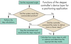
3. Consider how the SoC handles intermediate requests and how that will affect the design’s response when it’s installed in its application. Intermediate requests are when the application or a sensor requests a change in angle position before the motor completes its previous move. Here, the new command usually needs the motor to make fewer or more steps than previously calculated to correct for an error. If the new request is for more steps, the SoC determines whether full, half or microsteps can be added. The decision is partially based on what the motor is currently doing — if it’s accelerating or decelerating using micro, half, or full steps, for example. The SoC makes similar calculations when a new command requests fewer steps than the initial command. When the new position needs the motor to change the direction of rotation, the SoC makes new calculations and then stops and reverses the motor.
Tip: Always check that the motor can make enough microsteps to get through periods of acceleration and deceleration without slipping (or missing steps).
4. Note the frequency of the stepper motor. Keeping in mind that the frequency of the PWM signal is always constant to prevent slip, verify the effect of control ISRs. The timer interrupt dictates the motor frequency and shouldn’t have much code to execute. Therefore, when programming ISRs, have them just toggle certain flags. Then the rest of the control’s response and calculations can execute outside the ISR to maximize system speed and avoid crashes due to interrupt nesting. For example, ISR Code might read: void Timer8_PWM_DutyCycle_Update_ISR_C() {bBusy = 0;} void Timer16_Sensor_Input_Scan_ISR_C() {bFlag1=1;}. Likewise, code for an infinite while loop in main might read: while(1) {if(bFlag1==1) {bFlag1=0; Application_layer(); } if (bBusy == 0) {bBusy=1; Device_layer();} }.
5. Divide control functions into parts. It’s a good practice to divide all functions into PreprocessAPI(), ProcessAPI(), and PostprocessAPI() sections to make the programming modular. Then if a machine’s motor fails and the new replacement doesn’t require preprocessing before processing, the designer can just delete the preprocessing API.
Stepper-motor basics
A stepper-motor shaft (sometimes called a spindle) rotates in discrete increments when a sequence of electrical command pulses through the stator. The pulses’ sequence dictates the shaft’s direction of rotation and their frequency dictates the shaft’s rotational speed. Stepper motors are typically manufactured to output 12, 24, 72, 144, 180, and 200 steps/rev for 30, 15, 5, 2.5, 2, or 1.8°/step.
In full-step operation, the motor steps through the normal step angle. For example, a 200-step/rev motor takes 1.8° steps in full-step operation. There are two full-stepping modes. In single-phase full-step excitation, the motor operates with one phase energized at a time. That’s only suitable for applications in which torque and speed performance are unimportant, though — as when the motor runs at fixed speed and load. Resonance also precludes operation at some speeds, and this mode draws the least amount of power from the drive of any excitation modes.
In contrast, dual-phase full-step excitation drives the motor with two phases energized at a time for good torque (30 to 40% more torque than single excitation) and speed performance with minimal resonance problems (though requires twice the power from the drive power supply).
Half-step excitation is an alternate single-phase or dual-phase mode that spurs steps that are half the normal size for twice the resolution. This almost completely eliminates resonance problems. Motor-torque output varies on alternate steps, but the motor must only step through half its default angle at a time.
Designers usually only use microstep mode to get smoother motion or more resolution. Here, the drive divides the motor’s default step angle into very small angles (usually 1/10 to 1/256). So a 1.8° motor with 200 steps/rev driven at tenths of steps moves 0.18° at a time for 2,000 steps/rev. Microstepping at 1/256 gives 51,200 steps/rev.
Stepper-motor application: Pointer gages
Digital technologies abound, but on a lot of clocks and dashboards, information is still conveyed in analog formats. That’s because analog displays are intuitive. Consider pointer gages consisting of labeled faces and arms that point to values reflecting sensor measurements. Such gages abound in automobile, train, and modern aircraft dashboards, as well as industrial applications.
Usually, a mechanical system drives the pointer gage. A turning coil mounts outside a two-pole permanent magnet. Applied dc current causes a magnetic force that rotates the coil and attached gage pointer. Springs limit the coil-rotation angle, and the pointer-rotation angle is proportional to the coil current. Sometimes an oil damper suppresses oscillations during coil-angle setup to improve vibration resistance. The only drawback in this design is that oil dampers have operational temperature limits because oil viscosity changes with temperature.
Other gages use a bimetallic plate with a heater. This type consumes a lot of current during operation and ambient temperature affects readings. Still another design uses two quadrature-located coils to set the pointer position. These need a mechanical damper to prevent pointer flicker during vibrations. However, the newest and most-efficient option is to power pointer gages with the SoC-driven stepper motors as described in this article.
Resources: Cypress Semiconductor
