|
Key points: |
This file type includes high resolution graphics and schematics when applicable.
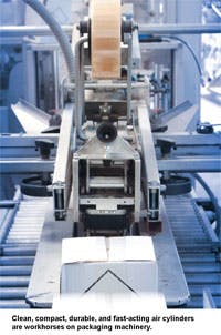
Wide acceptance comes in large part because cylinders are simple, economical, durable, and easy to install. They can produce thousands of pounds of force over a broad range of velocities; cycle at high speeds without overheating; and stall without internal damage. And they readily tolerate tough conditions such as high humidity, dusty environments, and repetitive high-pressure wash downs.
Pneumatic actuators come in literally thousands of styles, sizes, and configurations. This variety makes more innovative-equipment possible, but sorting out the best cylinder for an application can be a bit overwhelming. Here are some key considerations.
Cylinder design
The basic, rod-style industrial cylinder consists of a tube sealed by end caps. A rod attached to an internal piston extends through a sealed opening in one of the ends. The cylinder mounts to a machine and the piston rod acts upon the load.
A port at one end of the cylinder supplies compressed air to one side of the piston, causing it (and the piston rod) to move. The port at the other end lets air on the opposite side of the piston escape — usually to atmosphere. Reversing the roles of the two ports makes the piston and rod stroke in the opposite direction. Rod-style cylinders function in two ways:
Double-acting cylinders use compressed air to power both the extend and retract strokes, moving the rod back and forth. This arrangement makes them ideal for pushing and pulling loads. Controlling the rate at which air exhausts determines rod speed.
Single-acting cylinders have compressed air supplied to only one side of the piston; the other side vents to atmosphere. Depending on whether air is routed to the cap or rod end determines whether the rod extends or retracts. The most common type is pressure-extended, with an internal spring returning the piston to its original position when air exhausts. In other designs, gravity or an external spring powers the return stroke.
Rod-style cylinders come in various designs:
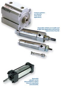
Sealed-for-life or “disposable” cylinders have end caps mechanically crimped to the tube. Internal components are prelubed prior to assembly. Although they are less expensive to manufacture than comparable repairable cylinders, they cannot be taken apart to repair without destroying the housing. These cylinders are usually used in lighter-duty applications and must be replaced when they fail.
Compact cylinders fit into smaller spaces where only a short stroke is required. They are used in lighter-duty applications due to the small bearing surface on which the rod slides. They mainly come in single-acting versions, but double-acting styles also are available.
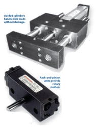
Guided cylinders have guide rods and guide blocks mounted parallel to the piston rod, or dual piston rods. They prevent the piston from rotating and provide precise, controlled linear motion — especially when the unit is subject to high side loads. In such cases, the guides reduce rod and piston bending and uneven seal wear. They are recommended in applications with sizeable offset loads or require that the load be guided, for example, down a conveyor.
Rack-and-pinion units convert a cylinder’s linear motion to angular rotation that can exceed 360°. The rotary actuators — with the rack mounted on the rod — are often used in process industries to operate quarter-turn valves.
Bellows are durable, single-acting actuators with flexible, reinforced-elastomeric walls and metal end plates. They extend when inflated and can generate high forces, thanks to their large diameters. A cylindrical shape lets them bend in any direction, making them useful where load direction might curve. Note that external restraints should be used to limit maximum extension and compression. Unrestrained extension can blow off the end plate, and exhaust without restraint can let the load crush the sidewalls.
Rodless cylinders, as the name implies, have no rod extending through the end caps. Instead, an external carriage slides back and forth on the tube. The load mounts on this carriage. In many designs, an internal piston is mechanically connected to the carriage through a sealed longitudinal slot in the cylinder wall. Long sealing strips inside and outside the cylinder tube prevent air leaks and dust and dirt ingression. Other variations include cable-and-pulley arrangements and magnetically coupled pistons and carriages.
Rodless cylinders are well suited for applications with long strokes or high moment loads. They save space because the stroke is contained within the cylinder’s overall envelope. Most manufacturers offer several carriage designs. Three of the most common are internally guided, externally guided, and precision-roller guided.
Force output
Another key selection criterion is how much force a cylinder generates. Determine this from the air pressure and bore size (the ID of the cylinder.)
A general rule of thumb is that for vertical and high-friction applications, the required force should be twice the load to be moved. In some cases additional force is necessary to compensate for friction.
Designers can calculate cylinder force by multiplying the effective piston area by the working pressure. The effective area for push force is the cylinder bore. For pull, it’s the bore area less the cross-sectional area of the piston rod. Thus, theoretical push force is:
F = π(D2/4 – d2/4)P
where F = force, lb; D = cylinder bore, in.; and P = pressure, psi.
Theoretical pull force is:
F = π(D2/4 – d2/4)P
where d = piston rod diameter, in.
Force calculations get more complicated in single-acting cylinders with a spring. The force opposing the push or pull increases as the stroke progresses. In practice, manufacturers’ catalogs often list push and pull values for both double-acting and single-acting cylinders, simplifying calculations for users.
When estimating the relative force of cylinders with different bore sizes, remember that thrust increases with the square of the diameter. In other words, doubling the bore will quadruple the thrust.
Speed
Speed affects productivity, longevity, and controllability. Calculate the stroking speed of a pneumatic cylinder from:
s = 28.8q/A
where s = speed, ips; q = airflow in standard cubic feet/minute; and A = piston area, in.2
Other factors that might affect speed include port sizes, inlet and exhaust flow through control valves, and hose or tubing sizes — if they create bottlenecks that restrict air flow to or from the cylinder. Likewise, air pressure that is barely capable of moving the load will hamper speed.
With any fixed combination of valve, cylinder, pressure, and load, it is usually necessary to have adjustable control over cylinder speed. Flow controls at the cylinder ports let users tune speed to their application.
For most applications, unidirectional flow regulators installed to restrict flow out of the cylinder and permit free flow in give the best results. A regulator in the rod-end port controls extension speed, and one on the cap-end port controls retraction.
Air consumption
It’s best to ensure the compressor has sufficient capacity to supply pneumatic equipment under “worst-case” conditions. Otherwise, air starvation at critical times will cause performance to suffer.
After sizing a cylinder for force and stroke, engineers have a lot of leeway in tweaking a cylinder so it best fits an application. Here are a few considerations.
Port sizes and locations are usually dictated by bore size, but can be adjusted in custom designs.
Envelope dimensions. The National Fluid Power Assn. and International Standards Organization have established standards for many cylinder dimensions, letting engineers interchange cylinders from different manufacturers. Many models also have unique dimensions.
Mounting configuration refers to how a cylinder attaches to the adjacent equipment. The large number of standard mountings — both rigid and articulated — usually ensures a cylinder can execute the specific movements an application requires.
Cylinder materials. The operating environment is the major factor that governs material choice. Pneumatic cylinders are typically made of steel, aluminum, stainless steel, brass, or engineered plastics. Some models combine several materials.
Seal materials. Cylinder manufacturers use a variety of methods to seal the end caps and rod. Designers can specify alternative seal materials for applications that operate in extreme high or low ambient temperatures or are exposed to caustic chemicals.
Position feedback. Magnetic cylinders have a band of magnetic material around the circumference of the piston and a nonmagnetic cylinder barrel. The magnetic field travels with the piston as the rod strokes in and out. Mounting reed switches on the outside of the barrel — one at each end, for example — generates a signal each time the piston completes a stroke. More-advanced versions use LVDT transducers or LRT linear potentiometers to provide continuous indication of piston position.
Cushions. If the piston makes metal-to-metal contact with the end covers, the result is noise and potential mechanical damage. Cushions in cylinders prevent such contact. Adjustable cushions let operators control the rate at which cylinders decelerate at the end of stroke.
Some cylinders have integral fixed cushions. They have a preengineered fixed cushion orifice that restricts exhaust airflow to slow the piston at the end of stroke. The amount of cushioning is repeatable but cannot be altered in the field.
Only use noncushioned cylinders at slow speeds. To operate noncushioned cylinders faster, install external stops with shock absorbers. Position these to prevent contact between the piston and end covers.
Cautionary tips
An important design consideration is to keep cylinder thrust as close as possible to the centerline of the piston rod and free from misalignment or side thrust. Cylinders are normally intended to push and pull without excessive side loads. Off-center loads can substantially reduce the service life of rod bearings and seals.
Off-center and side loading are caused by improper mounting, cylinder deflection under load, machine frame deflection, and rod bending or sagging — as well as by poor machine design. Sometimes adding an optional internal stop tube can reduce a cylinder’s bearing load. A stop tube is a spacer between the piston and rod-end head. It increases the distance between the piston bearing and rod bearing when the rod fully extends. This configuration also helps in long-stroke applications.
If the piston rod sees compressive axial loads, care must be taken to ensure its length, diameter, and load are within safe limits to prevent the exposed rod from buckling.
Most pneumatic cylinders are assembled with a coating of grease on the bore of the barrel and seals for service with nonlubricated air. If the compressed air supply is clean and dry, the grease will give the seals a long life without adding oil through an airline lubricator. However, contaminated air will gradually compromise the original grease lubricant and shorten seal life.
Lubricated air will extend the life of the cylinder, but it will also wash out the original lubrication. So once lubricated air is introduced, it must always be used, and the lubricator should be regularly checked and maintained.
Engineering custom actuators
For instance, Norgren’s Engineering Advantage team uses a full range of motion and fluid-control technologies to solve problems and create products that offer a competitive advantage. The results are often better performance, reliability, and uptime, as well as lower overall equipment and operating costs. Here are a few examples.
Baghouse cylinder. Air-pollution-control equipment that uses fabric tubes, envelopes, or cartridges to capture, separate, or filter dust is known as a “baghouse.” A power-generation plant needed to routinely close off chambers in its baghouse with a pneumatic-cylinder that provided quick, repeatable response, could adapt to various applications, and include all the required pneumatic and electronic components.
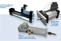
Engineers combined a standard NFPA cylinder with a directional valve, air filter, pressure regulator, and electrical wiring with junction box to build the baghouse-cylinder assembly. The unit was factory assembled and tested. The customer only needed to run control wires directly to the terminal block — saving time by eliminating the need to wire all individual components.
A mechanical lockout lets the cylinder isolate individual chambers within the baghouse for maintenance. Mounting the valve and electronics directly to the cylinder provides quick response and reduces air consumption. In addition, the space-saving combination leaves room for other components in the air-pollution-control system.
Unit-air assembly. Combining a cylinder, valve, and base in a single, compact unit produces fast response, saves space, reduces air consumption, and simplifies installation and maintenance. The package can be used in industrial applications such as packaging, material handling, printing, and paper converting.
Reciprocating-air motor. This cylinder/valve combination has stroke-signal valves that serve as external pilots. It is used to pump media such as lubricants, fiberglass, foams, resins, hot-melt glue, liquid polymers, waste gases, and other liquids. The cylinder’s quick response time assists dispensing. The self-contained package simplifies installation.
