Meeting portable design requirements with reflective encoders
Over the past few years, semiconductor companies have increasingly focused on the medical device market. Here, an emerging trend is the increase of home-managed care versus inpatient therapy — in turn, fueling the need for medical device manufacturers to develop products that are portable, affordable, and user friendly. More specifically, diagnostic and therapeutic devices such as dialysis equipment, portable insulin pumps, insulin inhalers, and diabetes management systems are increasingly accepted self-care medical devices, and are driving device manufacturer innovation.
To meet the challenge, product designers are integrating specialized components that suit small medical devices. Case in point: Miniature reflective encoders are proliferating in portable medical devices because, among other reasons we will explore, these motion feedback devices consume less power than traditional magnetic encoders.
Motion feedback objectives
Portable medical device design usually begins with building a list of product requirements based on market needs and conditions. In most circumstances, tradeoffs must be made between component sophistication and cost.
Weight and size - Medical devices labeled “portable” imply that they are easily carried — so size and weight specifications are critical. Therefore, portable medical devices requiring precise mechanical positioning benefit from lightweight reflective encoders for accurate position tracking.
Most commonly, a rotary version of such an encoder is attached to the back of the motor used to drive a series of mechanical systems. Alternatively, a linear encoder is used with a codestrip that has a series of black and white tracks on it. Here, the encoder is mounted on the system's moving part for motion tracking.
Resolution, frequency, and accuracy - Another set of criteria for selecting the right motion feedback device is the sensor's ability to provide suitable resolution, frequency, and accuracy. For a rotary system, resolution is the total number of steps representing one revolution of motion — often measured as counts per revolution (CPR) — or, for linear applications, as lines per inch (LPI). Higher CPR does not necessarily imply better accuracy in the design or indicate any detailed information about potential cycle error. A rotary encoder's final output resolution is determined by its module's count density and the size of the matching media or codewheel. The relationship between encoder output resolution (CPR), codewheel size (often expressed as optical radius, or Rop), and encoder count density (measured in LPI) is:
LPI = CPR/2 • π • Rop
A 6 mm-diameter housed optical encoder can offer at least 50 CPR pre-quadrature resolution or higher — or this can be quadrupled with external electronics to obtain post-quadrature output.
An encoder's frequency rating determines how fast the motor can spin without the encoder losing count. A typical miniature dc motor is rated around 20,000 rpm or lower at no-load conditions, with typical applications running around 6,000 to 10,000 rpm. At a rated motor speed, a typical 50 CPR encoder will need to have a frequency rating of at least 16.7 Khz or higher.
Page 2 of 2
The best cycle error from a typical magnetic encoder system with an interpolator is roughly three to four times higher than that of a comparable optical encoder system.
Power consumption - Engineers who design battery-powered portable medical devices strive to minimize total component power consumption.
Optical reflective encoders consume less power, prolong battery life, and offer greater flexibility for the selection of other components.
Cost and EMI - Portable devices for home use must be affordable — so their components must be priced in line with consumer markets instead of medical and industrial markets.
However, motion controls often comprise a large portion of the design budget due to the relatively high cost of precision motion components and lack of options.
Case in point: Mechanical encoder mounting requires special expertise and assembly tools — so medical device manufacturers often rely on motor manufacturers for an encoder solution, which typically ends up being a traditional magnetic-based encoder. Reflective encoders require no such mounting, as emitter and receiver are together in one unit.
On a similar note, because motor manufacturers often base their encoders on custom discrete magnetic technology, electromagnetic interference (EMI) is a potential problem. EMI issues have become more significant in recent years due to the proliferation of sensitive electronics in many devices and wireless communication tools such as cell phones, WiFi, and radio transmitters.
Reflective encoder technology leverages the behavior of light and optics, so it offers better immunity against EMI interruption, which in turn boosts safety.
For more information, contact Avago Technologies at (800) 235-0312 oravagotech.com.
How reflective encoders work
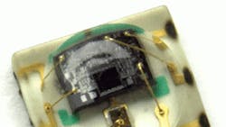
A reflective encoder consists of three major components — a light emitting diode (LED) light source, a detector integrated circuit (IC) consisting of photodiodes, and a lens to focus the emitter's light beam plus light falling on the detector.
In short, the detector's photodiodes sense the absence or presence of light. The rotary or linear motion of the monitored object is converted to an equivalent light pattern via a codewheel or codestrip. Consider the former: Here, the reflective areas (or windows) of the codewheel reflect light back to the photodetector IC; the non-reflective areas (bars) reflect no light. An alternating light and dark pattern corresponding to the window and bar falls on the photodiodes as the codewheel rotates. The moving light pattern is interpreted by the encoder's detector circuitry to produce digital outputs representing the rotation of the codewheel. When the codewheel is coupled to a motor, the encoder outputs are a direct representation of the motor's rotation.
