Understanding center-driven web winders: Part 2
Four classes of center winders are in general use: speed-regulated, dancercontrolled (see “Understanding Center- Driven Web Winders—Part 1” PTD, 4/95, p. 27); speed-regulated, load-cell controlled; torque-regulated, load-cell controlled; and open-loop, torque-regulated winders (see Table).
Speed-regulated, load-cell controlled winders
A typical block diagram for a load-cell controlled winder, Figure 1, is almost identical to that of a dancer-controlled winder except that a load cell replaces the dancer. Instead of regulating dancer position, the load-cell winder control directly regulates web tension. Thus, the effects of dancer inertia and stiction are eliminated. Also, because mechanical considerations of the dancer are eliminated, system design is simplified.
A load-cell controlled winder should not be thought of as a dancer with little accumulation. There is a substantial difference between controlling a dancer that has inches or feet of material accumulation versus a load cell which may go from 0 to 100% torque with only thousandths- of-an-inch movement.
When a dancer-controlled winder operates there is usually some dancer movement. Small movements occur during steady-state, constant-speed operation; larger movements occur during acceleration and deceleration. Even the smallest of these movements could cause web tension to go to 0 or over 100% of the load-cell rating.
With a load cell, the total movement from zero tension to full tension may be only 0.008 in. Controlling winder speed, in relation to the previous section, within this amount of movement is difficult. Since there is no accumulation, load-cell winder control is more exacting than is dancer control. First, the feed-forward speed calculation must be accurate. The more accurate it is, the less correction is required by the PID loop in the load-cell feedback path. Second, the winder drive system must have high performance. Winder control systems that use an adaptive- gain function to compensate for changing roll diameter and inertia provide the best performance for speed-regulated, load-cell controlled winders.
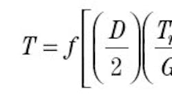
However, two performance factors often limit the use of this control strategy. First, fast acceleration rates are usually not possible. A machine with a dancer winder that accelerates from 0 to 2,000 fpm in 3 sec, may need 30 sec to accelerate with a load cell. Second, when nonextensible materials are wound, a slight instability in web tension often occurs. In spite of these drawbacks, the use of speed-regulated, load-cell feedback systems is increasing. Open-loop, torque-controlled winders A speed-regulated winder contol provides a speed reference to the drive system. The drive system follows the speed reference by providing as much torque as required, up to the limit of the drive or motor being used. An alternate approach, Figure 2, using torque control provides a torque reference to the drive system. The winder control receives three external signals: winder speed, line speed, and tension reference. Inside the winder control, a software model of the winder uses these external signals to calculate the amount of motor torque that is required to provide the desired web tension. The winder model typically takes into account web-tension reference, roll diameter, static friction, dynamic friction, and inertia compensation. Additional parameters can be considered if a more accurate winder model is desired. Openloop tension control is more accurate with sophisticated winder models. The desired motor torque is a function of the winder-model parameters, expressed mathematically as:
where:
T = Calculated motor torque
D = Roll diameter
Tr = Tension reference
G = Gearbox ratio
FG = Gearbox friction compensation
FS = Static friction compensation
FD = Dynamic friction compensation
IC = Inertia compensation
Roll diameter, the most important parameter, is calculated by dividing the line speed by the winder speed. The internal scaling of the control is set so this ratio is one when the winder is at core. Thereafter, if the winder is operating at onehalf of the line speed, then the roll diameter is twice the core. If the winder is running at one-third of the line speed, the roll diameter is three times larger than core. With this system, any roll diameter can be calculated.
As an alternative, encoders can be used to similarly calculate roll diameter. Or, the diameter can be sensed directly using a lay-on roll, press roll, rider roll, or an ultrasonic sensor.
Once the diameter is calculated, the web tension reference can be used to calculate the first term in the torque equation. The roll diameter divided by 2 is the roll radius, which is the effective lever arm. This radius times the web tension (in total pounds or other unit of force) gives a torque requirement at the input to the gearbox. This value divided by the gearbox ratio gives the motor torque required for this term of the equation.
Next, are added terms for: gearbox friction, static friction, and dynamic friction. The motor must deliver sufficient power to the winder to overcome these frictional requirements (related to mechanical operation of the winder) or web tension will be less than desired.
Since all gearing produces friction (worm gears more than other types), and friction is usually related to gearbox speed, more torque is required to make the gearbox turn as gearbox speed increases. Good winder controls make up for this friction, usually with a compensation that is linear with gearbox speed. Maximum gearbox torque is that required to turn the gearbox at maximum line speed at core diameter. Required gearbox friction compensation is this maximum value times the percent of maximum speed that the gearbox is running.
On systems that do not measure winder speed directly, this value can be calculated as:
where:
FG = Gearbox friction compensation
CM = Maximum compensation
LA = Actual line speed
LM = Maximum line speed
DC = Core diameter
DA = Actual diameter
Static friction compensation is required to compensate for the starting friction of the system and is usually set by increasing the motor torque as high as possible without having the winder begin to rotate. With this setting, the addition of only a slight amount of torque will start the winder rotating. This adjustment is independent of speed.
Dynamic friction compensation compensates for speed-related friction and is often a function of the square of the speed. This is similar to the torque requirements of centrifugal loads such as fans and some pumps.
The final term is inertia compensation. When the line speed of the machine increases, the motor must provide additional torque to accelerate the roll. The required torque depends on the inertia being accelerated and the speed change being made. The amount of time that the additional torque is required is the same as the acceleration time.
Inertia compensation is often misleading because it is not intuitively obvious. The intuitive approach says that as the roll diameter increases, the inertia compensation torque required to accelerate the roll also increases, Figure 3a. However, torque required to accelerate the roll can decrease with increasing diameter, Figure 3b. The inertia of the roll increases with diameter but, to reach any given line speed, the speed change that the roll must make decreases with increasing diameter. Thus, the entire mechanical system must be considered to determine the predominate effect.
It is also possible for the torque requirement to decrease with increasing diameter, and then to increase, Figure 3c.
The predominate advantage of openloop, torque-controlled winders is that good web-tension control can be achieved without the use of a dancer or load cell for feedback. A second advantage is that the control system tuning is not sensitive to inertia changes, because it does not use a speed regulator. No speed loop compensation is required with this type of winder.
There are disadvantages to this type of winder. First, web tension cannot be measured without adding a load cell. Second, if a web break occurs, the winder tends to run away at high speed and special protective functions must be added to the system to keep this from happening. Third, the system requires a multivariable setup. Although most of the setup is not difficult, it can be more complicated than that of a speed-controlled system. Also, machine dynamic friction compensation is difficult to set up properly without load-cell feedback. Fourth, this type of control does not work well with all mechanical systems. For instance, if the static friction of the system requires significantly more torque than the web tension requires, control problems can occur.
An experienced application engineer can be invaluable when considering this type of control.
Torque controlled winder with load-cell feedback
The configuration of this type, Figure 4, is the same as that of an open-loop, torque-controlled winder with the addition of a load cell and feedback loop. A winder model in this system predicts the torque that is required by the motor while web tension is measured by the load cell. Any error between the set-point tension and actual tension is used as input to a PID control loop whose output modifies the output of the winder model. In this way, motor output torque is continuously regulated to keep web tension equal to set-point tension.
Usually, the same winder model used in a torque-controlled, open-loop winder control is also used in the control configuration with feedback.
The advantages to this type of control are the same as those of an open-loop control. But, in addition, web tension is directly measured and directly controlled. Also, the machine dynamic friction term of the equation is easier to set up. Finally, since a speed loop is not used in this type of control, control system response time is fast—generally ten times faster than in the speed-controlled winder with load-cell feedback. The faster control loop, coupled with the predictive capabilities of the winder model, allows this type of control to have fast acceleration and deceleration times that are comparable to those of dancer-controlled systems.
The disadvantages of this system continue to be its more complicated setup and the additional protective functions required to prevent a runaway after a web break.
Mark S. Dudzinski is chief executive officer of Amicon, Inc., American Industrial Controls, Charlotte, N. C.
About the Author
Voice Your Opinion!
To join the conversation, and become an exclusive member of Machine Design, create an account today!

Leaders relevant to this article: