20 Minute Tune-Up: Closing the loop on linear motors
Direct-drive linear motors, as discussed in Tune-up, November, 1999, can run circles around mechanically interfaced shafted motors. They’re quick, silent, and accurate. They’re also highly reliable having few moving parts, and less prone to mechanical resonance. With all these advantages, you may be wondering what the catch is. For many designers, it’s selecting and mounting a feedback device.
With traditional shafted motors, it’s easy to take feedback for granted. In most cases, rotary motors include the feedback in the stator frame, so you don’t have to think about machining tolerances and assembly procedures associated with sensor mounting. Often – since the sensor is hidden in a sealed chamber within the motor – you don’t even have to be concerned with contamination.
With linear motors, the feedback sensor is typically located out in the machine. This translates to higher accuracy, but it also means more headaches. For example, you now have to consider the effects of contamination as well as the tolerance requirements of the sensor. In addition, you have to be more careful about cost; some linear-motor feedback sensors cost more than the motor itself.
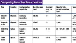
Sensors used with linear servomotors are often based on inductive, magnetic, or glass scales, or reflective (steel) tape. Each consists of a scale spanning the travel of the machine (up to 100 ft or more for tape) and a small read head that attaches to a moving member. Information from the scale, picked up by the read head, is converted to position feedback.
Linear feedback devices differ in the way information is passed from the scale to the read head. Magnetically coupled sensors – inductive and magnetic types – are usually lower in cost and less sensitive to contaminants such as cooling fluid. Optically coupled sensors – reflective tape and glass scale types – provide higher accuracy and resolution, but are more expensive. They’re also prone to failure by contaminants that block light, although (sealed) housed versions are available.
Another difference among sensor types is the dimensional stability required for the gap between the scale and read head. As a machine moves, you can count on there being an undesirable motion component perpendicular to the direction of travel. Some linear feedback devices are insensitive to this, others are not. For example, magnetic scales typically allow a 0.7-mm (0.028-in.) gap variation, while glass scales may be limited to less than a third of that. If the machine will see significant temperature changes, thermal expansion and contraction will also have an effect on the gap.
Accuracy is another consideration. Since there are no gearboxes or pulley-and-belt sets with linear motors, accuracy depends only on the tolerances of the machine and feedback sensor. Glass scales are top performers here, offering accuracy as good as 500 nm measured over one meter of travel.
Resolution is also important, affecting accuracy as well as noise. Servo loops usually hold position to within two or three counts of sensor resolution, so the lower the resolution, the less accurate the system. Low resolution also translates to noise, as it produces irregularities in the position signal which generate velocity, and hence, current spikes. Resolution as fine as 10 μm can cause audible noise, as we will see in the Lab session.
Fortunately, it’s not difficult to improve resolution. Linear sensors, like rotary encoders, produce signals that repeat as the motor moves. The length of the cycle, determined by the grating period of the scale, is related to resolution. Usually, resolution is at least four pulses per grating period, but it can be greatly increased by dividing (interpolating) the output signal into smaller parts as if it were an analog signal.
Although most encoder makers offer interpolation boxes, check your servo drive before you invest. If it accepts “sine encoder” signals directly, you may be able to interpolate on the drive, saving money and space.
A final consideration when using linear feedback devices is speed. Top speed is limited mechanically as well as electrically. For most sensors, mechanical limitations are pretty straightforward as read from a data sheet.
Electrical limitations, stemming from the ability of the read head to sense and convert “tick” marks, are a little tougher to figure out. Naturally, there is a limit on the output frequency that the read head can produce. It’s a function of mechanical speed as well as the grating period. Obviously, the finer the grating period, the faster (in terms of output frequency) the read head needs to be.
Resolution’s calming role
Want to learn more about sensor resolution? Then log on to www.motionsystemdesign. com and download this month’s ModelQ simulation program.
Launch the program, click “Run,” and you will be looking at a scope output of a simulated linear motor system with very high resolution. The system is moving a 2-kg load using a 10 N/amp motor; the servo gains (Kvi, Kvp, Kff, and Kp) are tuned up for very high bandwidth.
Notice that the current (black) is very smooth. That’s because the system has a resolution of 1 nm. Now, drop the resolution (“Res,” at left) to 10 μm (10,000 nm) and notice the jagged edges appearing in the current. The spikes indicate that the system would be quite noisy, negating the advantages of a direct-drive linear motor.
George Ellis is Senior Scientist at Kollmorgen Inc., Radford, Va., where he does research and design in motion control. His new book, Control System Design Guide, (2nd Edition), is scheduled to be published by Academic Press this Spring. You can contact George at [email protected]. Special thanks to Frank Locascio [email protected] for providing much of the information in this article
