Course Audit: Retaining Rings
Trouble-free connection of components to shafts, in housings, or on bores — essential for torque transmission and position maintenance — is simplified with retaining rings. However, the effects of thrust loading must be taken into consideration during design. Shearing and stressing due to deflection are two ways in which a retaining ring can fail; the type occurring at the lower thrust load limits design.
Shearing
Although shearing is not a typical failure, it can occur when:
• the ring is installed in a groove and loaded with a retained part, both subjected to loads exceeding compressive yield strengths.
• the load is applied through a retained part and groove with square corners and line-to-line contact.
• the ring is too thin in proportion to its diameter.
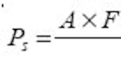
To check for the possibility of ring shear, check the allowable thrust based on shear strength of the material:
Axial deflection from overstressing
Grooves generally yield before rings shear. Twisting moments occur when the groove material’s compressive yield strength is exceeded and the ring is allowed to deflect axially.
The maximum stress on a ring subjected to this twisting moment is a tensile stress on its inside diameter. If the ring is stressed beyond the yield point, the ring will tend to grow in diameter and become dished in shape.
To determine the thrust load capacity of a ring based on groove information, the allowable angle of ring deflection must first be calculated. For internal rings,
For external rings, the equation differs slightly to account for the allowable angle of ring deflection.
For values of Φ equal to or greater than 18°, using 18° is valid. Otherwise, the resultant value from the equation for Φ should be used; experimental data indicates that rings have a tendency to pop out of their grooves beyond 18°.
The thrust load, based on groove yield, can be found:
Groove depth, chamfers, and radii
Manufacturer’s specifications for total radius of chamfer to be used in an application are simply guidelines for designers. Still, these guides can assure the validity of published or calculated static thrust loads.
Retaining rings used where specific limits are exceeded will show a marked decrease in thrust load capacity unless the groove depth, ring width, or compressive yield strength of the groove material is increased. Thrust load capacity is directly proportional to the groove depth. The effects of an excessively chamfered or rounded diameter can be minimized with a washer between the retained part and the retaining ring. Washers must be strong enough to withstand dishing under load.
Eccentric loading
The static, uniformly applied load is the type usually considered for most applications. However, static eccentric loads are frequently encountered due to design or tolerance stack-up problems.
Eccentric loading often occurs and is not usually anticipated by designers. Eccentric loads have two causes: either the face of the retained part is not parallel to the retaining ring because of a machining error, or cocking of the retained part (due to some external force). In the first case, the retaining ring and groove will often deform sufficiently to provide uniform loading on the ring. The second scenario, which is often encountered when a retaining ring is used to hold larger gears or hubs on a splined shaft, occurs when imperfect gear tooth meshing will cause the retained gear to cock. In situations where this might cause a problem, testing is recommended to verify designs.
Vibration induced by impact loading must also be considered. If the frequency of the system coincides with the resonant frequency, the ring can fail. The critical resonant frequency in the radial direction can be determined:
Centrifugal capacity
Proper functioning of a retaining ring depends on the ring’s ability to remain seated on the groove bottom. However, centrifugal loading can overcome initial cling built into an external ring and cause it to lose its grip on the groove bottom. To avoid this, the allowable steady-state speed of a retaining ring should be determined by using the following equation for carbon steel:
Due to their mass, larger diameter rings (typically over 3 in.) are often prone to spinning in their grooves when subjected to sudden acceleration. A ring which has spun in its groove will exhibit bright spots or a wear line along the surface which contacts the groove wall. A ring having increased cling to the bottom of the groove may be used as long as the installation stress is within permissible limits. If the loads are such that this will not suffice, precision locking mechanisms can help solve this problem.
Rotation between parts
The use of spiral wound rings to retain a rotating part should be limited to applications with light thrust loads and rotation in only one direction. External rings should be wound in the direction of the rotating part. Internal rings should be wound against the direction of rotation. Failure to achieve this setup will cause rings to wind out of their grooves.
Retaining ring grooves
To help maximize the ring thrust capacity, the walls of retaining ring grooves should be perpendicular to the shaft or bore diameter. The grooves should have square corners on the top edge and radii at the bottom within the tolerance specified by the manufacturer. Test data indicates that ultimate thrust capacity is greatly affected when these conditions do not exist. This is true for both static and dynamic loading.
In most applications, grooves are located near the end of a shaft or housing bore to facilitate installation and removal of rings. If the groove is located near the end of a shaft or a bore, it may shear out. To determine the edge margin, the general rule of thumb is to remove three times the groove depth away from the end of the housing or shaft.
Chris Clark is a design engineer at the Spirolox Division of Kaydon Corp., Fenton, Mo.
