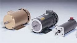
How efficient is your servomotor?
As the cost of electricity goes up, energy efficiency becomes more and more relevant as a design parameter. This is even the case in motion/position control applications, where servomotors are widely used. Unfortunately, many people overlook servomotor efficiency because the motors themselves are usually fairly streamlined. However, a misapplied servomotor can overheat and waste energy just like any other motor. It’s the application that makes the difference, and if you think it through you’ll get it right.
Defining features
First, however, let’s get on the same wavelength by defining what a “servomotor” is. The single most noticeable feature about a properly designed servomotor is that it is physically compact. For a given output, a servomotor can be anywhere from 25 to 50% smaller than other motors. For example, an ordinary 1-hp ac induction motor is typically around six inches in diameter. By comparison, a 1-hp SCR-rated motor is about five inches in diameter. A brush-type servomotor is four inches, and a brushless servo is three and a half inches square. The servomotor’s small size reduces rotor inertia, providing the fast response necessary for motion control applications. It also conserves energy.
Another characteristic feature is a feedback device. Servos require feedback to operate properly. This allows for closed-loop control and improved accuracy.
Compared to other motors, servos are also more carefully manufactured. More wire is wound onto the laminations, thoroughly filling the space between the teeth. Slot fills range from 75 to 80%, compared to less than 65% for most other motors. Although it presents a production challenge, a higher slot fill provides additional torque and greater efficiency.
A servomotor designed by these standards is typically over 85% efficient. Anything less, and the motor is probably not fit for a “servo” application.
Efficiency gauge
Since true servomotors are already efficient, the real measure of efficiency is the application itself. Every servomotor application is described by a set of performance plots. Each motor has a unique set of curves containing information about speed, torque, voltage, and thermal conditions. These curves, when considered in light of the intended load and duty cycle, tell how efficient an application is likely to be.
Torque curves — which everyone should be familiar with — let you determine operating speed from load torque and voltage. Thermal curves tell you under what circumstances a motor will run at its maximum operating temperature (usually 155°C). If the motor operates continuously on either side of the curve, it will run cooler or hotter. Inside (or under) the curve is the safe operating area. Outside the curve the motor will overheat (if operated continuously).
Efficiency curves also provide valuable information. They show the difference between input and output power over the recommended operating range. In motion control applications, servomotors should operate within this range to achieve high efficiencies.
Red zones
In general, there are two operating areas where servomotor efficiency tends to decline. One is at high torque and the other, low voltage. Both extremes are encountered in everyday applications, and you need to be aware of them.
Servomotors are most often employed because of their ability to produce high peak torque, thus providing rapid acceleration. But in achieving high torque, servomotors typically have to run two to three times higher than their normal (continuous) torque range. Here, servomotors must sacrifice efficiency by an amount depending on the design.
Low voltage losses can also be an efficiency factor in servomotor applications. Servos are designed to operate over a wide range of voltages. This is how their speed is varied. But when the voltage drops so does efficiency.
Continue on page 2
Efficiency guidelines
To ensure optimum servomotor efficiency, the following guidelines can be quite helpful.
The first thing to note is that servomotors have a very flat efficiency curve over their design range. So, trying to “buy” efficiency by running your motor at a relatively low torque — say, 40 to 50% of continuous stall torque — can actually turn out to be wasteful. If the low torque is really your operating point, you should consider using a smaller, less expensive motor.
Another bit of practical advice is to make sure your motor doesn’t exceed its thermal curve when operating at more than 90 to 95% of continuous stall torque. Otherwise, it will overheat. In addition, be sure to connect and use the motor’s internal thermal switch and the protection it provides.
Luckily, peak demands are intermittent. Most of the time — certainly for the average of the application’s duty cycle — servomotors operate in their high efficiency range, saving electricity and money.
How to read speed-torque curves
In constant-speed applications, motors are defined primarily in terms of horsepower, which is simply torque at base speed. Servomotors, however, tend to operate over a wider speed range, involving different torque regions. Servomotor speed-torque curves thus consist of two segments, continuous torque (defined as torque that won’t overheat the motor) and peak torque (defined as intermittent or acceleration torque). They also incorporate scales showing current (torque) and voltage (speed).
Consider, as an example, a servomotor application requiring 30 lb-in. of continuous torque at a speed of 3,600 rpm. Assume the peak torque required for acceleration is 80 lb-in.
The accompanying curve verifies that the servomotor in question can do the job. If the requirements are as follows — bus voltage = 300 Vdc, continuous current = 7 A, and peak current = 18 A — the motor can use a 10 A (continuous), 20 A (peak) control with a 230-Vac input (300 Vdc bus).
“Rated” conditions refer to measurement points and are selected as a convenient “reference” point for the manufacturer. During tests, manufacturers select a “rated” voltage and torque to verify that “rated speed” is reached. Any voltage may be applied as long as the design limits are observed.
