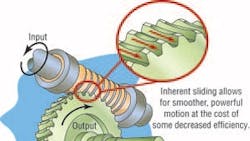
Worm gears are a power transmission standard, driving millions of axes requiring more drastic speed reductions. In this type of gearing a longer, more cylindrical worm (which resembles a screw) engages a flatter, more discus worm gear, also known as a worm wheel. The worm typically acts as the driver, and the wheel as driven axis. Unlike other gear designs, worm sets are usually unidirectional: while a worm can drive its wheel, worm systems should not be wheel-driven. This is because worm angles are often so shallow that static friction resulting between the worm and wheel holds the system in place. (Though this acts as a crude brake, it is not recommended to use the worm system as a braking mechanism — auxiliary backstops, holdbacks, and conventional brakes are the safest choice.) The worm wheel axis is at a right angle to the worm axis, and both are hobbed to mate. How teeth are cut determines the direction of rotation. The worm is typically threadmilled or rolled, while the worm wheel is hobbed to mate.
Worm gear sets are the most common right-angle reducers. The speed ratio of the two engaged shafts is large — generally over three, but sometimes even to 300:1. Relatively small worm gear sets can produce these large speed reductions with high torque output; geometric advantages such as large shafts, stronger worm and wheel materials, and one-stage gearing also help achieve higher ratios. However, singlereduction drives are inherently less inefficient — as low as 60%. Some newer worm gear sets utilize multiple gear stages to accomplish the same overall ratios, but at efficiencies up to 97%.
Globoids
Often worm gear sets are made so that the teeth of the worm, wheel, or both are curved. A gear with this profile partially wraps around its mate for increased tooth mesh. Called enveloping or globoid, these gear sets are preferred. Specifically, the double-globoid worm gear has been the dominant design since the 1920s. Double-globoid sets feature not only curved-top wheel teeth, but also hyperboloid worm teeth to better mate with the wheel. These features yield higher load capacities, because meshing several gear teeth at once multiplies transmitted torque. But many teeth in mesh is accompanied by reduced areas of tooth contact — and in turn, limited torque-carrying gains. (For this reason double-globoids are less common outside the U.S.) Lubrication between the worm and gear is improved with this design because of better mesh contact directions relative to worm rotation. The tradeoff here: for improved mating the worms of double-globoids must be made with special, costlier tools.
Double-globoids are sensitive to axial displacements (for example, caused by thermal warping) and require better mounting accuracy than standard cylindrical worms. The mating area between wheel and enveloping worm elongates for a small portion of the wheel width. As a result, the sliding speeds of the upper and lower mating zone areas are very different. Accurate assemblyis crucial (in the relative direction) to make sure alignment is accurate. The median wheel axis and worm axis must line up; more so, the median worm and wheel axes. Misalignments create load concentrations that increase wheel pitting and abrasion. Though the precise amount of wear depends on input speed, rubbing increases with reduced output.
Cylindric worms on globoid wheels have proven a suitable compromise. Such systems offer most of the benefits of double-enveloping systems while avoiding some of the drawbacks. They are widely used in servo applications, especially for precision handling, servo feeding, and high-performance adjustment axes.
Tooth and nail for performance
Tooth forms for worm gearing are not as standardized as other gear systems. In the U.S. worms are typically machined with a straight-side grinding machine, while in other countries worm members are commonly involute helicoids. Another difference: wheel pitch diameter divided by worm pitch diameter is almost never equal to their ratio. (Instead, the number of worm gear teeth divided by the number of worm threads determines the ratio.) Due to the tendency of wheels to wear and seat into worms, common factors between the number of worm threads and wheel teeth are avoided; this prevents repeated, identical engagement and concentrated wear in one location.
Of all worm tooth shapes, the involute is the most common. Because they are easy to manufacture, they are widely available and described in detail in AGMA and DIN standards. The worm teeth are usually thinned to fight backlash. But even after three-quarters of a century, worm gearing is not fully optimized; research continues to uncover design advantages. What is the worm’s biggest challenge? Sliding worm teeth provide smooth operation, but at the cost of generated heat. This lower efficiency (and higher rate of wear) has been addressed with increased leads. Newer vee-shaped teeth also improve performance. A slightly hollow flank profile is key: For any given transmitted torque, the large contact area minimizes the Hertzian stress (or surface pressure) on the worm. This makes for higher nominal, acceleration, and emergency- stop torques. Improved torque transmission between worm and wheel also increases efficiency, minimizing power loss, which allows for higher speeds in continuously running applications. So significant is the new design that the DIN standard in Europe is being changed to include it.
Special thanks to Ralph Whitley, Director of Engineering Boston Gear (of Colfax) for helpful input.>>(617)328-3300.
About the Author
Elisabeth Eitel
Elisabeth Eitel was a Senior Editor at Machine Design magazine until 2014. She has a B.S. in Mechanical Engineering from Fenn College at Cleveland State University.
