"The effectiveness of a light-bulb transfer method can be measured by the amount of broken glass beneath the machine,” say engineers for Osram-Sylvania Inc., of Ipswich, Mass. They recently developed a robotic transfer system that maintains part-position synchronization while smoothly exchanging light tubes between two assembly conveyors.
According to Ralph Cooper and Ted Lezon, engineers at Osram-Sylvania, “Robotic transfers are the most troublesome areas for many machines.” For this light-tube application, Mr. Cooper needed a synchronized transfer system that could precisely extract tubes from one conveyor and flip them over for pickup by a second conveyor.
Transfer operation
The transfer system Mr. Cooper and Mr. Lezon designed uses two 8-ft long indexing tractor-chain conveyors to move light tubes between multiple processing stations, Figure 1. Between the two conveyors lies an assembly consisting of two pneumatic grippers connected to a rotary axis, which in turn is mounted to a linear axis.
Various assembly operations occur to one end of a tube while it’s on the first conveyor (A). The pneumatic gripper then picks up the tube and moves it along the linear axis while simultaneously rotating it 180 deg. The tube is then placed on the second conveyor (B), where the same assembly operations are done to the tube’s other end.
The transfer system uses brushless servos for rotation and translation mechanisms that actuate simultaneously to service the two conveyors. A cam profile path, calculated by Mr. Cooper from traditional motion profile formulas, links the rotate and transfer axes for smooth overlapping motion that, in turn, links to the motion of the main conveyor. As the main conveyor turns, the transfer robot and the second conveyor execute their cam profile paths.
Though Mr. Cooper successfully used mechanical cam transfer methods before, several factors of this design demanded electronic control:
• The tubes vary in length from 4 to 28- in. long. A height adjustment screw changes the height of the transfer mechanism center line with respect to the conveyors. The screw can be adjusted independent of the transfer robot and ensures that the tubes are gripped in the middle, regardless of their length.
• Careful tube movement requires soft-start algorithms to eliminate motion jerk.
• The second conveyor and the transfer device had to be slaved, or phase locked, to the first conveyor at all speeds, even when jogged manually by the operator.
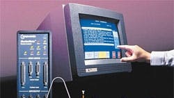
The chosen control also manages the servo axes, pneumatic grippers, error handling, and a touchsensitive operator interface.
Making converts
Initially, the engineers were hesitant to move to an electronic equivalent of cam profiling. “After all,” said Mr. Cooper, “mechanical cams have guaranteed physical clearances at all speeds and at all positions. We were not aware of an electronic cam control that could give us the same assurance.”
The cam profiler of the control, however, uses a position lock between master and slave axes that lets an engineer specify any arbitrary profile. Thus, the cam motion is predictable, precise, and reproducible at all operating speeds and at any point along the cam path. For the engineers, this feature assured the physical clearance of mechanical cams, but with the flexibility to store and use multiple profiles created in software.
Shorter development time
The control solved another problem — limited development time. The engineers were familiar with using a bus-based motion control scheme and integrating a rack full of cards, such as is necessary with a VME-based system. Mr. Lezon forecast the development time and resources he would need for the new system. He concluded that, even with having to learn a new control language, the control would shave a month off his development schedule.
About 18 months after they put in the new control, “Not one bulb has been broken in the new machine,” notes Mr. Cooper. “Fast transfer rates are accompanied by a more fluid motion of the two actuators, minimizing bulb motion jerk which could lead to breakage. In fact, the machine has been exempted from our internal problem tracking system, because there’s never been a problem.”
