Authored by: Edited by Leslie Gordon Resources: |
Most standard software for modeling magnetic fields uses the standard finite-element method. For some problems, however, an alternate boundary-element formulation can be much more efficient.
To understand the difference between the methods, it helps to recall a bit of theory. Magnetics fields are governed by Maxwell’s equations. Maxwell’s equations can be expressed in either differential or integral form. The two standard methods used for solving Maxwell’s equations in differential form are the finite-difference method and the finite-element method. The boundary-element method (equivalent to the method of moments) is the numerical technique normally associated with the integral form of a solution. Although both methods produce the same solution for a given problem, they are completely different. To illustrate this, consider a simple magnetic cylinder.
As its name suggests, the boundary-element method only requires that elements be on the boundary of the model being simulated. For the simple magnetic cylinder, there are a total of 12 boundary elements. The question is, how are these elements eventually used to calculate the magnetic field or other derived quantities such as force and torque? The answer lies in the integral form of Maxwell’s equations. A known current source lets us calculate the magnetic field at any point arising from this current by integrating the source along with the appropriate so-called Green’s function. Without getting into a lot of unnecessary mathematical detail, it is thus possible to calculate the magnetic field from current sources by doing some basic integration with the sources.
Under the hood, the boundary-element method replaces the magnetic materials with an equivalent surface current. Once this value is known, it can be treated the same as any real surface current. Thus, the goal of the boundary-element approach is to replace all magnetic materials with equivalent currents and then use basic integration to calculate the fields at any point. This sounds simple enough, but the actual implementation can be extremely difficult for certain classes of problems.
In contrast, the finite-element method requires a finite-element mesh in the magnetic cylinder as well as in the surrounding space. Theoretically, the mesh should extend off to infinity for an exact solution. Of course this is impossible, so it is necessary to arbitrarily decide how far the mesh should extend away from the cylinder to get an acceptable solution. This can be a major problem. Make the exterior region too small and the solution may never be accurate enough. On the other hand, the larger the exterior region, the larger the number of unknowns — hence, the longer the solution time. It takes an experienced analyst to judge the optimal size of the exterior region.
Assuming a proper mesh has been generated, the goal is to ultimately determine the magnetic field. To do this with finite elements typically involves first solving for a scalar or a vector quantity calculated at each of the nodes of the finite-element mesh. For magnetics problems, users typically calculate what’s called a magnetic-vector potential. This is an artificial quantity. To get the magnetic field, it is necessary to differentiate or take the curl of the magnetic-vector potential. This operation is in contrast to the boundary-element method where a user would integrate the unknowns to calculate the magnetic field.
A couple of examples should better explain both methods. Refer to the “Contour plot” illustration on the previous page. It shows an MRI machine with its magnetic field. You can easily see the coils used to generate the magnetic field. The goal is to have as uniform a field as possible near the center of the structure.
The problem of generating a uniform field at the center is ideally suited for boundary elements because there are no structural magnetic materials and high accuracy is a must. Use of the finite-element method would require placing the coils of the MRI machine in a large virtual “box.” The number of finite elements needed to get the same accuracy with the boundary elements, if at all possible, would be huge.
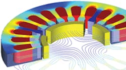
Now consider a permanent-magnet dc motor and refer to the “Field line and contour plot” illustration. This problem can be solved using either finite elements or boundary elements, but the speed of solution favors finite elements, provided a good 3D mesh can be generated in reasonable time. Finite elements would work well for the 2D equivalent of this problem because automatic mesh generators could be used with little or no user intervention. The bounding box for this kind of problem is relatively small compared to the size of the problem. Also, finite elements can handle nonlinear problems using far simpler and faster algorithms than boundary elements. In addition, volume elements are needed for boundary element solutions in any nonlinear region. This is a major downside for the boundary element method when solving nonlinear problems.
It can be seen that there sometimes is no “best” method for simulating a general magnetic-field problem. In some cases boundary elements work better, and in other cases finite elements are the better choice. Ideally, designers benefit by having the option to select the best method. In addition, software that includes both methods lets designers validate solutions by solving problems using two completely different formulations.
