Welcome to our first installment of Programmable Automation, a new department that will detail some of the most common ? and most complex ? motion-centric machine processes. This year, we'll explore topics ranging from web processing to path following, from registration to milling and drilling, and many others along the way. As a bonus, we'll not only show you with pictures and words, but with live visualizations on our web site. Each article will include a video link so you can see the machine process in action and get a better idea of all that's involved in creating these highly sophisticated motion profiles and sequences. Our first topic takes us into web processing and will focus on how to set up a flying shear.
Shear power
Web cut machines process materials such as fabrics, plastic sheet, and metal foils, cutting them to specific widths and lengths. The material, feeding continuously at high speeds, must be sliced on the fly, achieving higher throughput than would be possible with a stop-and-go operation. In the application described here, a carriage that holds a cutting tool must accelerate to the speed of the feed material (or web) before making any sort of contact. An electronic cam orchestrates the process, keeping the shear and conveyor moving in synch.
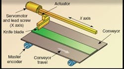
In a typical flying shear, the process material or web runs on a continuous conveyor driven by an open-loop motor. The shear, mounted on a servo-controlled carriage that moves along a track parallel to the conveyor, must accelerate to the velocity of the material to make the cuts in the right spots. After each cut, the shear must decelerate rapidly and get back to the starting position to begin the next cycle. Done correctly, flying shear operations produce uniformly spaced material sections of equal length without interrupting or slowing the line.
Flying shear web-cut machinery, like the type discussed here, usually incorporates three major electromechanical systems:
In-feed conveyor (master): The infeed conveyor, driven by an open-loop motor (the master axis), runs at a fixed speed independent of the controller. An encoder attached to the motor feeds position information to the motion controller.
Flying shear mechanism (slave): The flying shear axis, driven by a closed-loop servomotor, follows commands issued by the motion controller. The position of the slave axis is determined by the position of the master and the predefined cam profile. The servomotor connects to the knife through a lead screw, which synchronizes knife speed to that of the conveyor.
Knife: The cutting mechanism is a one-shot operation triggered by an output bit (from the controller) that fires a pneumatically driven knife downward into the fabric at the proper position. Other applications may use rotating knives or blades that cut across the material.
Design checklist
The primary elements comprising the motion system required for the application include:
- One axis to move the shear
- Forward and reverse limit switches (for the shear axis)
- Additional encoder input for the master encoder
- Electronic cam to simulate the motion of a mechanical cam
- Consistent material cut length (no registration eye required)
- Digital output bit to activate knife
- Standalone operation (no operator interface or host computer)
Motor and controller
Because it doesn't require a host computer, a standalone motion controller is the most economical and efficient way to implement the application. For maintenance-free operation, the system employs a NEMA 23 brushless motor, which generates all the torque that's needed (up to 0.3 Nm continuous) to drive the knife. A 1,000 cycle/rev incremental encoder is installed on the motor, achieving a feedback resolution of 4,000 quadrature counts/rev. Hall sensors aren't required on the motor because the encoder provides commutation tracks for the amplifier.
Motion management
The key to the application is the use of an electronic cam function in the controller. An electronic cam maintains a mathematical relationship between slave and master axes, simulating the motion of a mechanical cam. Usually, the master axis is a motor-driven axis or encoder to which one or more slave axes are synchronized.
The particular motion controller used here treats the electronic cam function as a table of slave versus master positions over the course of one cycle. The flying shear application defines one cycle as the distance the master encoder moves for one complete cycle of the slave axis (the cut length). The slave axis cycle consists of a rapid acceleration (to catch up to the conveyor), slewing (at speed) during the cut, rapid deceleration, and finally a return to the start position.
One of the advantages of an electronic cam over a mechanical model includes the ability to change the cut length and profile, on the fly if necessary, in software. Another benefit is that there's no need to swap out mechanical parts or cut new cams.
Program structure
It is assumed that the entire cam cycle has been defined at this point. For a detailed derivation of the cam table, visit www.galilmc.com/support/motioncode/flying_shear.html.
The final step in the design process is to put all of these pieces together into a program for the motion controller. See flowchart below for guidelines.
Special thanks to Galil Motion Control for this month's tips. For more information, visit www.galilmc.com or call (800) 377-6329.
Timing is everything
Once the knife blade reaches its correct position parallel to the conveyor, it makes a cut and returns home. The shearing motion must be perfectly timed in order to create uniform pieces of cut material, which proceed along the conveyor to the next machine process. An electronic cam is key to coordinating this motion with precision and accuracy.

