New software optimizes kinematics and plans paths for custom robots handling multiple axes. Flexible Robotic Environment (FRE) software was written by Bicommerce LLC, Rapid City, S. D., and it also acts as a motion platform.
To build a robot with FRE, the integrator selects compatible motors, drives, and mechanical parts. Direct and inverse-kinematics software calculates how motors on each axis must move to trace the robot’s end effector through preset points in space. Edits to the transformation matrix (relating the robot’s base coordinates to the moving coordinate frames) distribute the robot’s degrees of freedom to minimize position error. Then Application Programming Interface (API) software defines the motion profiles of the paths.
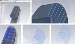
Developed for SolidWorks, the API is a graphical CAD-to-motion path planner called ModusCAM. Depending on the application, the API creates three kinds of paths: Stand-alone paths, typically to drive inspections; paths to clad surfaces of 3D solids (with laser deposition, for example); and paths to build solids slice by slice. The API can also plan paths for machining solids.
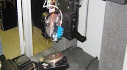
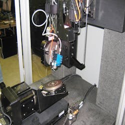
One machine built with the software is a six-degree-of-freedom (DOF) robot with motion components from Aerotech Inc., Pittsburgh. The VDK 4000 deposits metals, conductors, insulators, ferrites, polymers, adhesives, or biological substrate on silicon, glass, plastic, metal, ceramic, or polyimide parts. An end effector moves a 20-W YAG laser (with a spot size adjustable to 20 µm) around the workpiece to sinter on the deposit material.
The ModusCAM API (running on a custom HMI) maps workpiece geometry to a reference coordinate frame. After programming, the paths go to an Aerotech A2 controller with kinematics algorithms and I/O management routines for immediate execution. The A2 calculates setpoints for the control loops to synchronize the machine’s axes. Thermal models of the workpiece and deposition process adjust the control algorithm to optimize the material flow rate, laser power setting and melt pool, and end-effector speed. This improves the deposited layer’s microstructure to make a stronger part with fewer residual stresses.
FRE Distributor: Motion Maker Engineering.


