Designing with safety as a top priority ensures the longevity of machines and their human operators, and boosts productivity and profits. Here we review some of the latest protection products and offer tips on verifying and validating safety systems.
Safety relays suit industrial applications
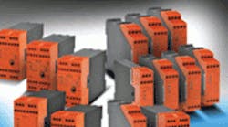
Dold safety-relay products abound: LG5924 Series single-channel E-stop relays protect people and machines in applications with emergency stop buttons; available with 24 Vdc, 110 Vac, and 230 Vac coil voltages. LG5925 Series relays are dual-channel E-stop and safety gate relays for applications with emergency stop buttons and safety gates; available with 24 Vac/dc, 110 Vac, and 230 Vac coil voltages. BG5933 and BH5933 Series relays offer protection for applications with two-hand buttons or production machinery with dangerous closing movements.
AutomationDirect
(800) 633-0405
automationdirect.com/safety-relays
Safety PLC monitors machine inputs
The eloProg programmable safety controller monitors machine inputs (photoelectric sensors, light curtains, emergency stop buttons, and safety mats) and then allows users to program the function of these inputs using icon-based software to create specific logic to control safety outputs. A flexible configuration allows inputs to be used for a range of functions, for example, a two-hand control or to connect an e-stop button. The base module can be operated as a safety controller without any additional modules, or may be combined with other modules to extend I/O.
elobau sensor technology Inc.
(847) 672-7515
elobau.com/Machine_Safety
Transducers ensure safety in solar installations
CTSR Series current transducers are suitable for use in safety-critical applications, including solar installations. Two transducers in the new series measure ac or dc leakage currents, from values as small as 300 and 600 milliamps, with spectral components to 9.5 kHz. Leakage currents can arise in fault conditions in many industrial or power-generation scenarios. Examples include solar panels coupled to an earthed grid, or in failure modes such as short circuits or earth faults. The CTSR family meets the latest safety standards regarding solar installations, VDE 0126-1-1, UL 1741, and IEC 60950-1.
LEM USA Inc.
(800) 236-5366
lem.com
Couplings protect against torque overload
Torq-Tender Overload Safety couplings protect critical rotating power transmission components from torque overloads and serve as both a safety device and coupling in a power transmission system. When a system's load exceeds the preset precision-tempered torque spring rating, the coupling's drive mechanism pivots out of an engagement slot, disengaging the prime mover from the load.
Zero-Max Inc.
800-533-1731
zero-max.com
Verifying and validating safety system designs
The lifecycle approach, as defined in standards IEC 61508 and IEC 62061, is the foundation for a systematic integration of both safety and machine functions early in the design process. That said, among the most important project phases are the final ones - verifying and validating the performance of the safety system design. By this point, the designer has already conducted an initial risk assessment, defined the machine's functional requirements, and started to design the safety system. Verifying safety performance means proving that the circuits for the machine's safety functions are working properly and meet requirements. Typically, engineers and electricians test the circuit while the machine is running: For example, they might activate an emergency stop (e-stop) to test that the machine indeed stops.
Completing validation involves testing that the system's safety functions work as intended. For example, in a dual-channel e-stop application using redundant control relays, a designer conducting the test might inject a human fault between the logic solver and output on channel one — activating the e-stop — to validate that the wiring is correct from the input to the logic solver. The designer would then repeat the process on the second channel to make sure it is functioning as planned. Validation takes place at both the machine builder's and end user's facilities to ensure that the safety-related control system functions correctly during machine commissioning.
Ultimately, designers must remember that verification is different from validation. Validating the system's safety functions requires a plan and documentation, and should include environmental, operational, and maintenance tasks. Validation proves that the safety circuit works correctly and requires fault injection during all modes of operation. It also requires circuit evaluation using analytical tools to verify circuit design compliance, component selection, and systematic analysis.
Safety system verification and validation must comply with global functional safety standards. Validation according to IEC 61508 and IEC 62061 means examining and testing the safety-related electrical control system, including hardware and software, to ensure it meets the application's functional safety requirements. The standards require a documented plan comprised of the validation's timeframe, the machine's modes of operation, acceptance criteria, and corrective actions to be taken in the event of failure. Validation according to EN ISO 13849-1 and 2 also entails a planned and documented process. It incorporates static and dynamic testing, among other methods, to show that all safety-related parts of the controls interact correctly to perform the intended safety functions.
This month's handy tips provided by Wayne Solberg, Certified Functional Safety Professional, Rockwell Automation. For more information, visitdiscover.rockwellautomation.com/safety.
