The roles flexible couplings fill are well known – they connect imperfectly aligned shafts and transmit torque, with or without backlash. Such devices are necessary in many systems and available in numerous forms to fit the function.
Another type, the more basic rigid coupling, is ideal for a wide range of applications as well. Numerous innovations continue to refine this component.
Rigid introduction
Rigid couplings are just that – rigid. They are meant to connect two shafts so they essentially become one. They will not accept misalignment, and so are not intended for shafts that are mechanically fixed (by pillow blocks, for example). They’re good for overhung and extended loads like those seen in pumps and mixer paddles. Long, unsupported shafts are also prime candidates for rigid connectors.
The two elementary rigid coupling styles are machined set-screw, for smaller shafts, and ribbed, two-piece cast, for larger and higher horsepower applications. The ribbed style, all but unchanged, remains the coupling of choice for large shafts, but it is uneconomical for shafts two inches or less in diameter. The machined, set-screw coupling is basically a cylinder with a keyway and set screws. From a simplistic viewpoint this is a sound design, but in practice its shortcomings become evident. It can loosen under vibration, and set screws can leave dents or dimples in the shaft or keyway, deforming the surface so that adjusting or removing the coupling becomes difficult. While hardened shafts may resist dents, they also can prevent set screws from locking and properly holding in place. And with set-screw couplings, keyways are necessary for torque transmission, thus the phase relationship between coupled shafts cannot be changed.
Engineers handling smaller applications – up to two-in. diameter – are often moving away from traditional (set screw) rigid couplings to assimilate a broadening range of designs, most of which are based on clamping. Clamping couplings don’t damage the shaft surface, they serve on hardened shafting, and they maintain hold under vibration and cyclic or reversing loads. Also, assembly and adjustment are not generally a problem.
Giving the squeeze
The simplest clamping coupling is a cylinder bored to fit snugly over closetolerance shafting. Slots and clampscrews are located to create two independent clamping areas. The coupling will clamp down around the shaft circumference when the cap screws are tightened, and static friction between coupling and shaft keeps them turning together.
This holding friction is influenced by the number of cap screws, the applied axial force along the each of these screws, and the coefficient of friction between contacting coupling and shaft surfaces. Axial screw force is a function of screw thread lubrication and tightening torque, while the frictional coefficient is affected by the hardness, lubricity, and finish of contacting surfaces.
The torque capacity is established by the frictional hold as well as by the shaft diameter. Bear in mind, however, designating couplings through analytical methods will mean juggling many variables. Often a more practical and stable approach is to read into manufacturers’ published tables based on actual physical testing.
Rigid couplings are intended to bring two shafts together with no runout (radial misalignment). For minimal runout in clamping couplings, clamped portions of shafting are smooth and without blemish, they fit snugly into the coupling bore, and the clamp screws are tightened gradually and sequentially to allow proper shaft seating.
Clamping coupling styles
Beyond the basic rigid clamping design are variations incorporating principles like adaptability, easy installation, higher torque, and phase adjustment.
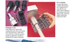
Stepped bores allow coupling of shafts with different diameters, even metric and inch combinations. Shaft adapters are similar, attaching onto a shaft end to provide a male output, thereby converting shaft size.
Installation and removal is often facilitated by “breakaway” designs. Two-piece, axially split couplings assemble around shafts without requiring either of them to be moved. Triple-split couplings are also axially split, and one of the halves splits again laterally, so one shaft can be adjusted without disturbing the other’s attachment to the coupling.
High torque can be handled in several ways. Keys can be used to reinforce clamp-style couplings whose frictional hold might otherwise eventually slip or give out. Keys and keyways therefore allow additional torque throughput for a comparable coupling size, even while they fix the angular relationship between shafts. Heavy-duty couplings, on the other hand, are made larger than standard, using a higher quantity of bigger clamping screws to increase torque capacity without keyways. Heavy-duty couplings are suited for applications with frequent reversal, impact, and vibration – things that can overcome a lesser frictional holding force or break a key.
Phase-adjusting rigid couplings are specifically made to allow fine-tuning of the phase relation between coupled shafts as well as associated components like gears, cams, and sprockets. The clamp screws are loosened and the coupling outer shell is turned to change the shafts’ angular orientation. Rotating the coupling usually translates into a much smaller amount of shaft movement. For instance, with a 100:1 ratio a complete coupling revolution would only turn the shaft 3.6°.
Arthur Stafford is President of Stafford Manufacturing Corp., Woburn, Mass.


