As we look at catalogs of electric motors, we find them classified by power, speed, and torque. To a large extent, the motor diameter tracks the power output. There are some very practical reasons related to the manufacturing of motors that puts the focus on the motor diameter. However, the constraint of diameter also imposes functional limitations. Reviewing the history, science, and practical issues behind motor manufacturing reveals the patterns driving this practice.
History of Motors
The primary historical item related to electric motors is that of magnets. Initial discovery of magnetism started with lodestones, very weak, naturally-occurring magnets. Next came electro-magnets made of iron laminations with copper wire coils around them. Later, alnico and ferrite (or ceramic magnets) were incorporated. Since magnets were expensive and not overly strong, motor designers tried to use iron to contain, direct, and focus the magnetic flux in the motor.
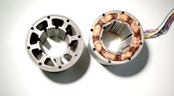
A problem with magnetic iron is eddy currents that generate iron losses. To limit these losses the iron needs to be made into thin plates known as laminations. These laminations are punched, stacked, and bonded together to form magnetic structures such as the motor stator shown below.
In concept this is relatively simple, but from a manufacturing point of view, the larger the diameter, the bigger the punch press, and the bigger the required punching die. The larger the initial sheet of metal, the more scrap there will be; a small motor contains less material, so it is less expensive to mass-produce. Roughly speaking, the cost of the capital equipment and the material content of the motor increases as the square of the motor radius. This cost function creates economic pressure to constrain the diameter of the motors.
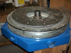
Empire Magnetics 30-in. diameter, axial flux, brushless DC motor/alternator to be installed in a windmill hub. As an alternator this unit produces three-phase 220 VAC, 3300 watts, at 180 RPM.
Magnetic iron is relatively cheap as a bulk material, but the machines needed to punch, stack, glue, and grind these metal components are expensive. Today, setting up a motor manufacturing line that can produce quality products at competitive prices requires an investment greater than $20 million, and a factory that will produce multiple motor sizes can easily exceed $100 million in capital investment. For this reason, many of the old production lines are still operating as investors capture as much revenue as they can from the installed equipment.
Key Terms to Better Understand Motors
Another, less-obvious reason why older designs linger is that few designers have the educational background to take advantage of the new materials and manufacturing techniques. In particular, the strength of rare earth magnets has significantly changed the design options.
To understand this, it’s helpful to review a few key terms:
Torque = Force × Length of a lever arm (aka moment arm = motor rotor radius).
If we increase motor diameter, we increase the rotor radius, and increase the motor torque even if the force generated by the magnets has not changed.
Power = Torque × Speed
Since a small motor has a short lever arm, the torque will be small; but if the motor turns a high speed, the output power can be significant. For applications where, continuous rotation is required (e.g., fans, pumps, and small-diameter motors), turning at high speeds are a cost-effective solution.
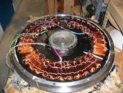
Placement of loop coils is shown, prior to casting of the winding assembly. Three sections (the pink, green, and blue wiring) are offset by 1/3 of magnet width to make three phases.
However, if the user requires slow speed and high torque, small high-speed motors can only be used with the addition of gearing or other mechanical torque multiplication devices. In addition to their cost, gearboxes or other mechanical devices introduce errors and efficiency losses into the system.
A second issue is thermal limits. The power throughput of an electric motor is limited by the amount of heat it can dissipate. A small motor has a limited amount of surface area, so it cannot dissipate as much heat as a larger motor. If we look at the heat generated in a motor, there are two primary sources: copper losses (amperes squared times resistance) and iron losses due to eddy currents. For a typical motor the iron losses are roughly equal to the copper losses.
With the advent of more powerful magnets, it is now feasible to make motors that don’t incorporate iron into the switched magnetic circuit. The primary effect of iron is to increase torque at low speed at the cost of motor efficiency at higher speed.
Ends of interlaced loop coils are shaped, so that sections between magnets are in a single plane. This reduces the air gap between magnets, increasing output torque.
A large diameter motor has more volume available for magnets and coils, which allows the designer to choose between maximizing torque, or maximizing efficiency by reducing power density. With reduced power density the temperature is more easily controlled which becomes critical if the purpose is to position to 0.0001 in. Many of the high-precision machine tools today are moving to direct drive motors as a way to improve accuracy of the parts they produce.
Elimination of errors in the mechanics also reduces parts, increasing machine reliability. The cost savings typically more than offsets the price of the larger motor while improving the functions of the machine.
Basic Configurations of Motors
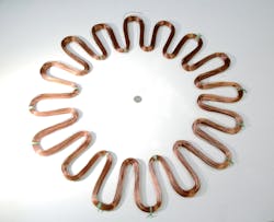
One of three windings that go into the large diameter axial gap (Axial Flux) motor.
For direct drive motors there are two basic configurations, radial gap (or radial flux), and axial gap (flux). Radial gap motors are cylindrical in shape, while axial gap motors are more pancake-shaped. To increase the torque of radial gap motors, the length of the unit is increased while the diameter of the axial gap motor increases its torque.
Since the magnet area is a primary factor in determining the torque, we can compare cylinder surface area (circumference of the rotor, times the length of the magnet stack, to the square of the radius times 3.14159 for the axial gap motor.) For motors of limited length, the axial gap unit has the advantage, while radial gap units are winners when a long cylinder shape can be used.
In practice, the center of the axial gap motor is typically hollow, allowing for hollow shaft designs. Many configurations are possible depending on the design goals. Embedded magnets support high rotational speed, while double rotor arrangement maximizes torque.
Richard Halstead is the president of Empire Magnetics.


