The last 20 years have seen precision amplifiers used for positioning and velocity control make major strides in power output, size, and control features. Applications such as laboratory automation, semiconductor equipment, and scientific automation make use of high-end amplifier capabilities such as field-oriented control. The cost of electronics is coming down to a point where even industries identified with basic motion needs now consider using high-end features, particularly where smoothness, motor efficiency, and top speed matter.
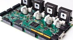
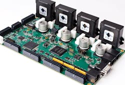
Another key development is that of solderable amplifiers, which let engineers build cards able to run an entire machine. It is even possible to obtain amplifiers that mount on the motor itself, a strategy that may simplify wiring.
It is helpful to review exactly what modern motion-control amplifiers can do. At their core, amplifiers accept low-power control signals and generate higher-power voltages to drive the motor. By far and away, the dominant approach in amplification for motion control is to generate drive signals through a technique known as pulse-width modulation (PWM), or just switching.
Switching amplifiers basically generate a variable duty-cycle square wave that is filtered to give the desired output signal. They take advantage of the ever-increasing efficiency with which metal-oxide field-effect transistors (MOSFETs) and insulated-gate bipolar transistors (IGBTs) can switch on or off, rapidly applying a bus voltage to a circuit load, and then disconnecting that supply from the load to produce a particular commanded voltage.
Though switching amplifiers dominate motion control, there are still some applications where nonswitching linear amplifiers (also called transconductance amplifiers) are needed. They are three to five time times less efficient than switchers, but linear amplifiers generate much less electromagnetic interference (EMI) and, thus, find use where that property is critically important.
Current control
Current control, also often called torque control in servomotors, refers to the active regulation of current flowing through each winding of the motor. Windings are inductors, so they resist changes in current. In addition, the motor itself is a highly dynamic environment that induces back-EMF (electromotive force) onto the winding as it spins. Both of these effects distort the actual current flowing through each winding relative to its applied voltage. Amplifiers with current control actively compensate for these effects to improve response time, efficiency, and positioning accuracy.
Is current control always critical? For stepmotors, the answer is yes because current control in steppers affects nearly every aspect of performance — top speed, positioning accuracy, heat generation, and more. There is a bit more wiggle room in dc-brush and brushless-PM-motor applications. But as costs have dropped for electronics and current-sensing hardware, active current control has become the norm for all but a small number of motion-control applications.
The term phasing refers to the selective application of voltage or current to the windings of multiphase motors such as stepmotors and brushless-dc motors. Proper phasing keeps these motors moving forward or backward as directed by the host controller. Dc-brush motors, by comparison, phase themselves using brushes or other contacts to distribute the applied voltage to the correct rotor coil as it spins. So dc-brush motors need no external phasing control.
Stepmotors employ various phasing schemes such as full stepping, half stepping and microstepping, depending on the step increment. For brushless-dc motors, phasing is called commutation. The most-common version uses feedback from Hall sensors positioned around the rotor shaft to generate trapezoidal or six-step drive signals. Trapezoidal commutation, while widely used, has discontinuities where the Hall-effect sensors switch. This has led to the wide use of vector control, also called field-oriented control (FOC), which uses a sinusoidal waveform along with more-advanced phasing algorithms. FOC provides smoother motion, more-efficient motor operation, and higher top speed.
As with current control, ever-improving controllers such as digital signal processors (DSPs) are making FOC a standard feature in more and more motion-control systems.
There are a number of additional functions that are likely to be important in modern motion-control designs. One particular area is fault detection. Look for detection/protection from overtemperature faults, short-circuit faults, overcurrent faults, bus overvoltage and undervoltage faults, and more. Properly designed, these features can protect an amplifier, motor, and sometimes even the machine in the event of a failure.
Another useful motion-amplifier feature is called I2t current management. This is a general technique for limiting the total energy delivered to the motor. Compared to instantaneous current limiting, I2t provides a much-more useful protection mechanism because heating comes from current applied over a period of time.
Beyond all these features there are, of course, the basic specifications of the amplifier itself. These include the voltage range, continuous and maximum current ratings, and environmental ratings such as temperature operating range. Needless to say, the amplifier needs enough get up and go for your application!
Modern controllers
Motion systems typically consist of three major components; the controller, the amplifier, and the motor/actuator. The controller is an integrated circuit or printed-circuit card that outputs control signals to the amplifier.
But what kind of signals? The granddaddy of amplifier command formats is ±10-V analog. In this scheme, the motion controller generates an analog voltage carried differentially over two signals that encode a desired voltage, current, or velocity. Typically, these signals are routed by cable to the amplifier module.
Unfortunately, analog encoding makes less sense when amplifiers incorporate DSPs and other digital logic. Why convert the controller’s digital signals to analog and then convert them back to digital in the amplifier?
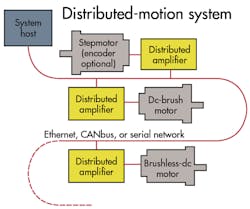
To address this conundrum, about 20 years ago general-purpose industrial networks began to host digital amplifier-command interfaces. Nowadays, networks hosting such interfaces include CANopen, Profibus, EtherCAT, Ethernet Powerlink, and a few others.
What does the controller actually say to the amplifiers? In some cases just the desired torque goes down the wire, but often the controller sends higher-level command streams such as PV vectors (position, velocity).
Once the interface becomes digital, the amplifier can report problems back to the controller and assist with tuning and setup. This ability has made possible new generations of module-oriented machine controllers where the location of the amplifier is practically a nonconsideration in the design of machines.
Network-based amplifiers seem like the ultimate evolution of machine controllers. But it’s worth remembering that what originally motivated the separation of the amplifier and the controller was the need to manage heat. Today, those same amplifiers no longer generate all that much heat.
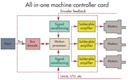
This sets the stage for what has become an increasing counter current to modularization: the tendency to locate all controls on a single control card. With all controls on a single card, there are fewer failure-prone connectors and cables. Ditto for service hassles: There is no need to figure out whether the motion card, the cable connections, or the amplifiers are causing the problem.
Improvements in switching amplifiers are the single biggest factor making such all-in-one machine controller cards possible. With less heat generated, a single control card can safely drive kilowatts of power rather than dozens of watts as in the past. A decade ago, engineers were forced to go “off-board” for higher power axes such as spindle control, centrifuges, robot arms, shuttles, and so forth. Now, they can buy off-the-shelf ICs or solderable modules and keep everything on a single printed-circuit board.
One major category of such products consists of small, dedicated, single-axis motor amplifier ICs. These ICs come in various configurations such as H-bridges (used with dc-brush and stepmotors) as well as half-bridges (used with brushless-PM motors). Basic entries provide just the switching function and perhaps some overcurrent protection. More-sophisticated versions provide current control and additional features such as selectable fast-decay, slow-decay operation.
For stepmotor control, these ICs directly produce pulse and direction signals and provide half-step as well as microstepping control. They utilize current control techniques especially suited to the demands of managing stepmotors.
An important drawback to this category of on-card amplifiers is that they rarely output more than 4 A or 150 W. In terms of drive sophistication. These products are fairly low on the totem pole. If they provide commutation, it is typically six-step trapezoidal, and many of the higher level features described earlier are missing.
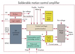
The other major category of on-card amplifiers pertains to solderable amplifier modules. Solderable amplifier modules resemble traditional cable-connected amplifier modules in that they embody a single packaged unit providing all the major functions discussed earlier — amplification, current control, phasing, and extras such as FOC and sophisticated fault detection.
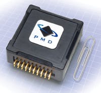
They differ from cable-connected amplifier modules in several important ways, however. For starters, they may be tiny, but some can produce up to a kilowatt. (Not bad for an amplifier occupying a bit more than a cubic inch.)
As the name implies, they are solderable. They generally use standard through-hole pin connections and packaging that tends to have around 20 pins. These pins provide microprocessor-compatible connections, power input signals, motor output, and other safety and control signals.
Unlike lower power amplifier ICs, solderable modules are full-blown motion amplifiers. In fact, many of the same companies that offer cable-connected amplifiers also offer solderable motion amplifiers. These products are well suited for positioning and high-precision velocity control.
With new paradigms come new challenges. Neither analog ±10-V signals nor full-blown digital networks are well suited for connecting to onboard microprocessors with solderable amplifiers. So what is the right format?
Some amplifiers directly output PWM waveforms, but doing so means the motion controller must perform the task of current control, a daunting prospect for many designers. The alternative is to settle for voltage-mode control of the motor windings, a major sacrifice in performance.
Another common approach retains some flavor of analog input. Most commonly, the module provides a unipolar analog level along with a separate digital sign bit.
The interface that seems to be gaining attention is serial-peripheral interface (SPI). SPI is completely digital and uses just four signals. Communications can be bidirectional and the bandwidth is more than enough for motion applications which tend to update the desired torque at a rate between 2.5 and 10 kHz.
There are other digital formats such as RS-232. There has been talk within the industry about whether a standard will evolve for on-card amplifier connections. Only time will tell.
Finally, amplifiers small enough to mount directly on the motor have made a big splash. Such a configuration is called an integrated motor drive (IMD) and has special benefits in the area of cable reduction. Encoder signals and Hall-sensor signals from the motor feed directly into the IMD and needn’t go back to the controller.
The downside of IMDs is that they boost the weight of the motor assembly, and IMD electronics are likely to get hotter than those of an amplifier sitting in a rack or in a controlled environment. The heat affects reliability or lifetime, depending on the harshness of the operating environment.
Edited by Leland Teschler | Resources — Motion-control basics | Motion-control study guide | Motion-control trends | Performance Motion Devices
