Additive Manufacturing in Aerospace and Defense: Process Selection, Materials Qualification and the Engineering Path to Flight-Ready Hardware
Key Highlights
- AM process choice determines material performance. LPBF, DED and metal binder jetting create distinct microstructures, residual stresses and defect profiles that directly affect fatigue life and fracture behavior.
- NASA has validated propulsion AM at scale. The RAMPT program logged more than 500 hot-fire tests and 16,000 sec. of operation on 3D-printed propulsion hardware.
- Aerospace AM qualification is becoming model driven. The FAA-EASA shift toward the CM4QC framework is moving certification from build-and-test to physics-informed computational qualification.
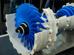
This article examines the technical foundations of AM adoption in aerospace and defense: how process physics governs material performance, how design engineers must adapt topology and geometry strategies to AM constraints, what the certification architecture actually requires at the component level, and where the field’s most consequential technical challenges (such as computational qualification and the digital thread) are heading.
Selecting the Right Additive Manufacturing Process: The Foundation of Aerospace Component Performance
The three metal AM modalities actively achieving flight qualification in aerospace—laser powder bed fusion (LPBF), directed energy deposition (DED) and metal binder jetting (MBJ)—do not differ merely in throughput or geometric capability. They produce fundamentally different solidification conditions, grain morphologies, residual stress states, and defect populations.
For a design engineer specifying an AM process, these are not secondary considerations: They are the primary determinants of fatigue life, fracture toughness and damage tolerance in service.
READ MORE: From Printer to Spindle: How Aerospace Components Actually Get Made
LPBF melts powder feedstock layer by layer using a high-power laser, producing layer thicknesses typically between 20 and 80 micrometers. The rapid thermal cycling—peak temperatures exceeding 1,600°C followed by solidification in milliseconds—creates steep thermal gradients that drive columnar grain growth along the build direction. This microstructural anisotropy is a defining feature: LPBF Ti-6Al-4V exhibits tensile strength that meets or exceeds wrought equivalents in the longitudinal direction but may underperform by 5-15% in the transverse direction, depending on post-build heat treatment.
Hot isostatic pressing (HIP) at 920°C and 100 MPa for two hours is the established protocol for closing sub-surface porosity and reducing microstructural anisotropy to acceptable levels for fatigue-sensitive applications. For LPBF components entering the FAA certification workflow, Advisory Circular AC 33.15-3 specifically addresses the use of powder bed fusion in turbine engine design, the only AM-process-specific AC the FAA has issued to date.
DED deposits material by melting a wire or powder feedstock directly onto a substrate using a laser, electron beam or plasma arc. Deposition rates are orders of magnitude higher than LPBF—measured in kilograms per hour rather than grams per hour—making DED economically unsuitable for high-resolution, complex-channel geometries but extremely effective for large structural preforms, repair of worn turbine blades, and cladding of wear surfaces on high-value defense components.
The coarser thermal conditions in DED produce larger grain structures and lower residual stress concentrations than LPBF, but surface finish is inferior and near-net-shape tolerance requires significant post-machining allowance. The U.S. Air Force has deployed DED for sustainment of legacy platforms including the C-130 Hercules and F-16 Fighting Falcon, where the process enables on-demand replacement of discontinued components without re-engaging an original tooling chain.
Metal binder jetting binds metal powder particles using a liquid binder agent at room temperature, followed by sintering. The process is laser-free, which reduces per-part energy consumption and eliminates the thermal distortion inherent to fusion-based processes. However, sintering-induced shrinkage—typically 15–20% volumetrically—must be precisely compensated in the digital build file and residual porosity levels after sintering remain a qualification challenge for fatigue-critical applications.
MBJ is attracting development funding for higher-volume production of secondary structural and non-structural components where throughput economics matter and damage tolerance requirements are less stringent.
Translating Process Capabilities into Aerospace Design Advantages
The most persistent misapplication of AM in aerospace engineering programs is translating a conventionally designed drawing directly into an AM build file. This approach forfeits the geometric freedom that defines AM's technical value proposition and retains the material inefficiencies of the original subtractive design. Design for Additive Manufacturing (DfAM) requires a fundamentally different workflow that begins with load path analysis rather than shape inheritance.
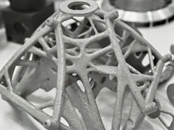
Topology optimization—the computational method for maximizing structural performance by selectively distributing material only within the load-bearing envelope—is the natural entry point for DfAM in aerospace. The engineer specifies the design space (the maximum volumetric envelope the part may occupy), applies boundary conditions representing the operational load spectrum (including combined static, dynamic and thermal loads) and defines an objective function (typically minimum compliance or maximum stiffness at a target mass fraction).
Finite element analysis solves iteratively across this design space to produce an organic, lattice-like solid that may be unproducible by any conventional process yet is directly buildable by LPBF.
Part consolidation is equally significant. Components that required multi-part assemblies—brackets with fastened gussets, heat exchangers with brazed manifolds, fuel injectors with welded passages—can be redesigned as monolithic AM builds, eliminating assembly operations, leak paths and joint-induced stress concentrations.
NAS’s Perseverance rover incorporated 11 3D-printed metal components into its final configuration, many of which achieved part count reductions of 3-5 sub-components through consolidation. The bill-of-materials benefit compounds through the program: fewer parts mean fewer inspection records, fewer supplier qualification audits and fewer failure modes in the formal FMEA.
Bridging the Gap Between Material Innovation and Flight Qualification
Flight hardware qualification in aerospace is built on statistically characterized material design allowables, strength, fatigue, fracture toughness and creep properties established across a defined range of temperature, environment and load ratio combinations.
For conventional wrought and cast materials, these allowables exist within Metallic Materials Properties Development and Standardization (MMPDS) databases and are accepted by the FAA as the basis for structural analysis. AM materials have not yet achieved equivalent qualification maturity and the gap defines the qualification bottleneck more precisely than any other single factor.
READ MORE: Additive Fusion Technology’s Impact on Manufacturing
Ti-6Al-4V and Inconel 625/718 represent the most mature AM alloy systems in aerospace. LPBF Ti-6Al-4V has accumulated sufficient test data across multiple machine platforms and powder lots to support allowables generation for certain applications, though machine-to-machine variability—driven by laser parameter drift, inert atmosphere oxygen content and powder recycling—remains a systematic challenge that prevents true platform-independence.
The AMS 4999 specification covers LPBF titanium components for aerospace, establishing minimum property requirements and process control documentation. For nickel superalloys, Inconel 718 processed by LPBF has demonstrated tensile properties meeting AMS 5662/5663 wrought equivalents after appropriate solution annealing and aging treatments but its high-cycle fatigue behavior is more sensitive to surface condition and sub-surface porosity than wrought material, requiring surface treatment protocols (machining, shot peening or electropolishing) as part of the qualified process chain.
NASA’s development of GRX-810 represents the frontier of purpose-engineered AM alloys. This oxide dispersion-strengthened medium-entropy alloy—a nickel-cobalt-chrome matrix reinforced with nano-scale yttrium oxide particles introduced directly into the LPBF feedstock powder—was designed specifically for the thermal and mechanical demands of rocket engine hot-section components.
Its oxide particle network inhibits dislocation motion at temperatures where conventional superalloys begin to lose creep resistance, enabling structural integrity in environments approaching 1,093°C. The alloy is not a retrofit adaptation of a wrought composition; it is geometrically and thermally optimized for additive production and its properties cannot be replicated by conventional processing routes.
Aluminum-lithium alloys are entering AM qualification programs for applications where structural stiffness-to-density ratio is the governing design parameter. Specific research programs, including NASA-funded efforts, have documented 15% higher specific stiffness in LPBF Al-Li builds compared to conventional cast-and-machined equivalents at equivalent mass.
The challenge is Al-Li's sensitivity to hydrogen pickup during powder handling: Moisture in the powder feedstock dissociates at melt temperatures, introducing hydrogen porosity that degrades ductility and fatigue life. Strict inert atmosphere handling of Al-Li powder and dehydration protocols before build are non-negotiable process requirements, not recommended practices.
Navigating Regulatory Requirements for Airworthy Additive Manufacturing Components
AM parts in type-certificated aircraft must comply with the same FAA regulatory requirements as conventionally manufactured components. The governing regulations under 14 CFR—specifically Parts 25.603 (materials), 25.605 (fabrication methods), and 25.613 (material strength properties) for transport category aircraft—do not distinguish between AM and conventional manufacturing. What changes is how compliance is demonstrated, because AM introduces process-property relationships that legacy compliance documentation frameworks did not anticipate.
For structural parts, the compliance demonstration must establish design allowables traceable to a controlled process specification. This means the AM process—defined by machine configuration, laser parameters, inert gas flow rates, powder specification, build orientation, support strategy, and post-processing protocol—must be locked and characterized before allowables testing begins.
Any change to a process parameter that the engineer cannot demonstrate is inconsequential to material properties triggers re-qualification: a new build parameter study, a new test matrix, new allowables. This is not a bureaucratic artifact; it reflects the genuine sensitivity of AM microstructure to process conditions in ways that forging and casting are not.
The Joint FAA-EASA AM Qualification and Certification Workshop, operating annually since 2018, is the primary forum where regulatory agencies, aerospace OEMs, materials scientists and national laboratories negotiate the technical boundaries of AM compliance methodology. The September 2024 session reviewed EASA Certification Memorandum CM-S-008 Issue 04, which outlines airworthiness compliance positions specific to AM parts.
The 2025 edition (held in Cologne, Germany) introduced dedicated working group sessions on model-based qualification, reflecting a consensus shift in how both agencies are approaching the scalability problem of part-by-part empirical qualification.
The Aerospace Industries Association’s 2025 Recommended Guidance for Certification of AM Components provides the most current industry-consensus framework for navigating this regulatory environment. It structures the qualification workflow around three tiers of part criticality—non-structural, secondary structural and primary structural—with corresponding test matrix depths, non-destructive evaluation requirements and process control documentation standards.
For design engineers preparing an AM part for certification, this document is the operational reference—not because it creates regulatory requirements, but because it reflects the methods the FAA currently accepts as compliance demonstrations.
Model-Driven Qualification and the CM4QC Framework
The fundamental limitation of build-and-test qualification protocols for AM is combinatorial: The number of process parameter combinations, machine configurations, part geometries and material lots that aerospace programs are generating exceeds the test resources available for empirical characterization of each.
A fighter aircraft nacelle bracket built in orientation A on machine X with powder lot Y is not the same material system as the same part built in orientation B on machine Z with powder lot W—and demonstrating that the difference is inconsequential requires either a prohibitive test matrix or a physics-based prediction of why the microstructure and properties are equivalent.
READ MORE: Additive Manufacturing Innovations Drive Industry Forward
The Computational Methods for Qualification and Certification (CM4QC) initiative—convened by a steering group comprising NASA, NIST and the FAA, alongside aerospace OEMs, defense prime contractors, national laboratories, and university research groups—is developing the formal framework for using validated computational models as recognized elements of the certification evidence package.
The technical foundation is the AM Bench program at NIST, which generates high-fidelity in-situ measurement data of AM build processes (temperature field evolution, solidification front velocity, melt pool geometry) to which process simulation codes can be calibrated and validated.
Establishing End-to-End Traceability Through the Digital Thread
The digital thread concept—a continuous, linked data stream connecting design intent, process parameters, in-process monitoring, post-build characterization and in-service performance—is not an information management aspiration in aerospace AM. It is an emerging regulatory expectation and a technical prerequisite for model-driven qualification.
In an LPBF build, every layer generates a thermal imaging record of melt pool geometry and intensity. Layer-by-layer powder bed imagery captures recoating defects and porosity precursors. Atmosphere sensors log oxygen content throughout the build. These data streams, linked to the specific build file, machine serial number, powder lot certificate and post-processing records, constitute a process pedigree that enables post-build traceability to in-service anomalies and provides the input data required to run process simulations calibrated to actual build conditions.
Broader Additive Manufacturing in Aerospace & Defense Market research consistently identifies digital thread implementation as one of the highest-priority technical investments among aerospace prime contractors, reflecting its centrality to both quality assurance and regulatory compliance workflows.
For design engineers, the practical implication is that AM process documentation is not an afterthought, but part of the design deliverable. A component’s design is no longer fully described by its CAD geometry, material specification and drawing tolerances. It includes the qualified process parameter set, the build orientation rationale, the support structure strategy and the post-processing protocol. Change any one of these, and the design has changed in a way that may require re-qualification.
Understanding this coupling between design decisions and process pedigree is the critical competency that separates engineers effectively deploying AM in flight programs from those re-learning it expensively mid-program.
Key Engineering Competencies Shaping the Future of Aerospace Additive Manufacturing
Additive manufacturing in aerospace and defense is not approaching a qualification inflection point; it has already passed one for certain component classes. LPBF titanium and nickel-alloy propulsion hardware is in flight service. DED-repaired turbine components are being returned to service on military fleets. AM-produced satellite structures are orbiting.
The field’s open technical frontier is not whether AM can produce acceptable hardware, but whether the qualification and certification frameworks can scale to the part diversity and production rates that program offices are now requesting.
READ MORE: The Future of Defense Engineering: Trends and Insights
For the design engineer, this means the required competency set has expanded. Deep knowledge of AM process physics—solidification microstructure, residual stress mechanics, defect formation mechanisms—is now a prerequisite for intelligent process selection and build parameter specification, not a specialization.
Fluency with topology optimization and DfAM workflows is the difference between a component that delivers AM’s geometric value proposition and one that merely replaces a machined part with an AM-produced equivalent at higher cost. And engagement with the CM4QC framework, the FAA-EASA regulatory architecture and the digital thread infrastructure is no longer optional for anyone working on programs that will seek flight certification.
The engineers who will define the next generation of aerospace hardware are those who treat AM not as a manufacturing alternative but as a design medium—one with its own physics, its own constraints and its own pathway from material to certified hardware.
About the Author
Shammi Thakur
Research Director, MarkNtel Advisors
Shammi Thakur is Research Director at MarkNtel Advisors with more than 15 years of experience in market intelligence, technology assessment and industry forecasting. He leads research across advanced manufacturing, aerospace, defense and industrial technology sectors, with a focus on emerging technologies, market evolution and innovation-driven growth strategies. His work combines technical analysis with market insights to help organizations navigate rapidly changing industrial landscapes.
Voice Your Opinion!
To join the conversation, and become an exclusive member of Machine Design, create an account today!
 Leaders Logo
Leaders relevant to this article: