Building a MEMS-Based Vibration Detector
Condition monitoring is a challenge for companies with mechanical facilities chockful of motors, generators and gears. But it is needed to give plant managers insights into how the mechanical equipment is performing and if it might need maintenance. Well-targeted maintenance can head off unnecessary downtime and long repair jobs.
One way plant managers carry out condition monitoring is by analyzing the vibration patterns emitted by their machinery. For example, vibrations from gearboxes are usually in the frequency domain as multiples of shaft speed. Irregularities in those frequencies point to wear, imbalance or loose parts.
Microelectromechanical system (MEMS)-based accelerometers are often used to measure frequencies such as these. Compared with piezoelectric vibration sensors, they have higher resolutions, excellent drift and sensitivity characteristics, and better signal-to-noise ratios (SNR). They can also detect low frequency vibrations close to the dc range.
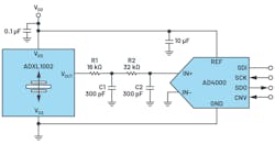
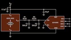
The circuit above is a highly linear, low-noise, wideband vibration measurement. The analog output signal from the ADXL 1002 MEMS accelerometer is fed via a two-pole RC filter to the successive approximation register (SAR) analog-to-digital converter (ADC) AD4000. It converts the analog signal to a digital value for further signal processing. This approach can be used for bearing analysis or engine monitoring, as well as all applications requiring a dynamic range of up to ±50 g and a frequency response from DC to 11 kHz.
The high frequency, single-axis MEMS accelerometer provides an output signal pass band that extends beyond the senso’s resonant frequency range. This lets frequencies outside the 3 dB bandwidth be monitored and measured. To accommodate this, the accelerometer’s output amplifier supports a signal bandwidth of 70 kHz. Capacitive loads of up to 100 pF can also be directly driven with the accelerometer’s output amplifier. For loads over 100 pF, a series resistor of less than 8 kΩ should be used.
The external filter at the output of the accelerometer is needed to eliminate aliasing noise from the output amplifier. It also takes care of noise from the accelerometer’s internal components that might arise, such as when they couple through the internal 200-kHz clock signal. So, the filter bandwidth should be implemented accordingly.
With the dimensioning shown in the circuit above (R1 = 16 kΩ, C1 = 300 pF, R2 = 32 kΩ and C2 = 300 pF), attenuation of about 84 dB is reached at 200 kHz. Also, the selected ADC sampling rate should be higher than the amplifier bandwidth (32 kHz, for example).
For the ADC, an accelerometer supply voltage should be selected for its reference because the output amplifier has a ratiometric relationship with the supply voltage. In this case, the voltage supply tolerance and voltage temperature coefficient (which are usually connected to external regulators) run between the accelerometer and the ADC so that the implicit error associated with the supply and reference voltages gets canceled out.
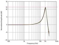
The frequency response of the accelerometer (shown below) is the most important characteristic of the circuit. The gain increases at frequencies above about 2 to 3 kHz. For the resonant frequency (11 kHz), the peak value for the gain is about 12 dB (factor of 4) in the output voltage.
To display measuring range overshoots (overrange), the accelerometer has a corresponding output (OR pin). The built-in monitor emits a warning when the output overshoots the defined range.
Special attention should be paid to properly mounting the accelerometer. It should be close to a rigid mounting point on the board to avoid vibrations on the circuit board which can cause measurement errors if undamped. Proper placement ensures every circuit board vibration on the accelerometer exceeds the mechanical sensor resonant frequency and is therefore practically invisible to the accelerometer. Several mounting points close to the sensor and a thicker board also reduce the effects of system resonance on sensor performance.
The circuit, which detects vibrations from the DC range to 11 kHz, as is often required in condition monitoring for rotating machinery, can be built relatively easily.
Thomas Brand is a field applications engineer specializing in the field of Industrial Ethernet for Analog Devices.
About the Author
Thomas Brand
Field Applications Engineer, Analog Devices
Voice Your Opinion!
To join the conversation, and become an exclusive member of Machine Design, create an account today!

Leaders relevant to this article: