Overcoming Common Integration Mistakes that Derail Automation Equipment Installations
For equipment manufacturers, a successful factory acceptance test is cause for celebration. However, many of the most significant engineering challenges occur on the plant floor, after the confetti and empty champagne bottles have been swept away.
Since an equipment manufacturer’s scope typically ends at the physical edge of the machine frame, critical facility infrastructure and integration responsibilities can often go undefined. And yet, it’s within this ambiguous gray area that costly delays crop up.
After all, a machine can be fully designed, built and factory-tested but still encounter engineering problems, because the interface between the machine and facility was never treated as a design issue. Identifying these challenges during project scoping, before detailed machine design begins, minimizes implementation surprises and maximizes the value of an automation investment.
Where the Machine Ends and the Facility Begins
Project documents may place an OEM’s scope at the edge of the machine frame, but manufacturing facilities don’t recognize that boundary. Floor conditions, building columns, power availability and pneumatic/hydraulic supplies all impose hard requirements on the equipment, regardless of who is contractually responsible. That is how ambiguity around ownership begins.
That ambiguity can expand when customers bring equipment installation and facility preparation in-house to reduce costs. That approach may have a certain short-term logic, but facility requirements often fall between ownership lines and go unaddressed until it’s too late to handle them cost-efficiently. Deciding at the start who owns each facility-related task helps ensure those needs aren’t missed.
However, specifying ownership alone isn’t enough for a successful startup. The team preparing the site also needs accurate input from other suppliers. Every subsystem and equipment provider on the line needs to define and share their equipment’s requirements early, before the design locks in. That includes electrical and air needs, floor conditions and leveling tolerances, not to mention the mechanical demands of the equipment itself.
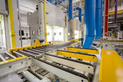
A conveyor, for example, can bind on an uneven floor. Its supplier can help the other stakeholders understand the equipment’s needs and plan the facility provisions around them. Even when a supplier isn’t responsible for the facility work, supporting the team that is responsible makes the project more likely to succeed. The machine-facility interface works best when OEMs, integrators and plant owners treat it as a shared responsibility.
Verify Facility Conditions Before Design
Ideally, a current, verified record of facility conditions, gathered directly from the plant, would provide a project team with a single basis for defining integration requirements. Unfortunately, facility documentation is often out-of-date. A layout drawing or a 3D scan could be a decade old and may not reflect recent changes.
This often leads to design decisions made around conditions that no longer exist. For example, equipment may have been relocated, new piping or ceiling drops installed or new mounting structures added. A less obvious but common example is power capacity. Plants often add new systems without documenting the increased draw, making it appear the facility has more power available than it actually does.
Similarly, not factoring in a facility’s washdown protocols—including the temperatures, pressures and chemicals used—can lead to seal failure or corroded materials. Even minor conditions can make a difference. A system being tested at a runoff facility with large windows may perform differently under the lower lighting in the customer’s plant.
Organizations also often overlook documenting vertical space when calculating a site’s total available space or may not consider how equipment will get into the building. On one large project, a multilevel conveyor system arrived at a plant where the only way in was down a narrow hallway. The conveyor system hadn’t been designed around that constraint, so the entire system was returned to the manufacturer to be cut into smaller sections for reassembly on the plant floor.
Unless teams recognize and resolve these types of site discrepancies, they may not surface until startup. The most reliable way to close these gaps is to verify facility conditions with the people who know them firsthand. Maintenance teams often know details that engineering teams and drawings miss. Involving them early improves the accuracy of the design inputs and begins transferring knowledge about how the new equipment works and will be maintained, better supporting its long-term usability.
Integrating Machine-level Controls with Plant-wide Systems
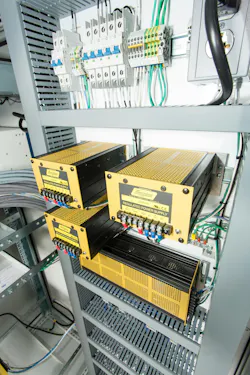
Connecting a machine’s programmable logic controller (PLC) to a plant’s manufacturing execution system (MES) or another plant-wide system starts with hardware selection. Choosing a PLC and interface modules that suit the plant’s network simplifies integration. Once communication is established, adding data points is generally straightforward.
The challenge, however, is deciding the scope of that connection: which data the machine will hand off and who is responsible for implementing each part of the connection. The potential for collecting machine and production data is broad, and integrations that try to capture too much become open-ended projects and lose focus on the problem they’re meant to solve. A clear data definition reduces ambiguity about what the system will report.
Planning for failure is also critical. If the plant-wide system loses contact with the equipment, the team needs to know whether the fallback is to stop production or continue with manual tracking. That decision affects the controls design, operator procedures and production continuity. The time to make that decision is during planning with the customer, not improvised on the plant floor after the first outage.
Avoid the Future-proofing Trap
While future-proofing is a legitimate design goal, it can overtake a project’s needs. Designing to open-ended requirements or an ideal future state can stall the current project, especially when those future needs can’t be specified. Rather than divert resources toward an ideal end state, teams can design in flexibility by defining a plausible minimum and maximum for future product specifications. Setting this range allows movement toward a broadly defined future state in phases.
The same holds for reserving space and sizing power drops. Sizing to a reasonable upper boundary has immediate costs, but they’re often lower than demolishing or upgrading infrastructure later. Collaboration among integrators, solution providers and end customers during the design phase can help define realistic boundaries that aren’t too restrictive or open-ended.
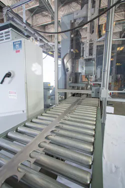
For example, an automation line carrying products in totes was specified for one tote size, yet a wider tote was planned to handle larger products in a few years. Ultimately, the automation line was designed with a wider conveyor and adjustable side guides so both sized totes could be safely conveyed through the line. Most teams won’t have future plans this clear.
Modularity and component compatibility are effective ways to design a system or facility that’s adaptable to an uncertain future. Building on common drives, transmission methods and conveyor platforms across equipment and project phases allows additions to extend the line more easily.
A consistent design creates a cohesive system with less overhead to operate and maintain, while mixed approaches and components across phases complicate integration. Within the machine itself, starting with a core architecture creates an adjustable base framework that stays constant while interfacing end pieces change, such as the adjustable side guides on the tote conveyor.
Even so, the most adaptable solution isn’t always the most cost-effective option. Each phase needs to be justified by its return on investment, rather than by how much flexibility it provides. The right amount of future-proofing doesn’t depend on what’s theoretically possible, but on the project’s budget and timeline, a facility’s anticipated future capacity, the equipment’s physical limits and the cost or complexity of later modifications.
Success Beyond Site Acceptance
The odds of equipment running smoothly from day one increase when OEMs, systems integrators and plant owners treat that outcome as an explicit project goal. When facility integration isn’t assumed, issues like space, structure, utilities and controls are addressed in the earliest planning stages. Gaps in real floor conditions or utility drops become more expensive and harder to fix the later they surface.
Bringing facility operations and maintenance teams into the initial discussions ensures critical plant details and failure modes are built into the design, not bolted on during startup. They can flag when a design is about to make maintenance access difficult and costly. When machine-facility integration is engineered deliberately, the vision of success looks beyond site acceptance testing to achieving reliable, supportable operations for the equipment’s working life.
Have a question, comment or idea? Get in touch with the Machine Design editors at [email protected].
About the Author
 Noah Bougie
Lead Instrumentation and Controls Engineer, ACS
Noah Bougie is Lead Instrumentation and Controls Engineer for ACS , which engineers, integrates and builds equipment, controls and facilities for leading companies in automotive, aerospace, energy, chemical and manufacturing.
 Scott Blais Jr.
Sales & Business Development Manager, mk North America, Inc.
Scott Blais Jr. is Sales & Business Development Manager for mk North America, Inc., which specializes in conveyor systems, pallet-handling solutions and modular aluminum framing for a wide range of industrial applications.

Voice Your Opinion!
To join the conversation, and become an exclusive member of Machine Design, create an account today!
 Leaders Logo
Leaders relevant to this article: