Why Analyzing Large Automotive HPDC Parts Using Traditional CAE Falls Short
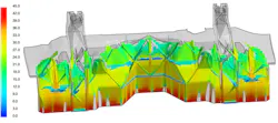
To meet electric vehicle (EV) requirements and achieve lighter structures, automotive manufacturers are increasingly replacing stamped assemblies with high-pressure die-cast (HPDC) aluminum parts. This poses a challenge for structural and design engineers, as conventional crash-simulation workflows often do not fully account for manufacturing effect.
HPDC parts offer numerous benefits, including reducing overall mass, part count and manufacturing costs. However, castings develop location-dependent mechanical properties driven by process variability that can cause serious structural concerns. Assigning a single stress-strain curve to the entire part ignores these casting imperfections and produces less accurate results that mask potential failure modes.
To complicate matters, the majority of these components are critical load paths—for example, rear floors, front rails and dash underbodies. As such, erroneous crash prediction data at this stage jeopardizes passenger safety and causes substantial rework in the design process. Before delving into an emerging methodology that addresses this, let’s examine the limitations of legacy approaches.
Why Traditional CAE Workflows Fall Short
During HPDC filling, molten aluminum encounters varying flow lengths, turbulence and thermal gradients. This can lead to a variety of potential defects, including oxides from surface-film entrainment, porosity from shrinkage or trapped gas and flow-length-dependent ductility degradation. Their implications extend far beyond simple cosmetic issues:
- Surface-film entrainment can cause degraded mechanical integrity, making the part more prone to sudden fracture under load.
- Porosity locally reduces density and pressure tightness, so that a component may lose stiffness or fail earlier than anticipated due to crack initiation and propagation.
- Ductility degradation can arise based on flow length, meaning a part may look structurally sound but have a weak structure with varying internal properties such as reduced yield stress.
These issues not only increase the likelihood of defects but also introduce considerable concerns about the part’s structural behavior in crash scenarios. Elongation-to-failure, the property most critical to crash energy absorption, can vary widely across a single part. Areas far from the gate or prone to last-to-fill conditions will behave differently from well-fed regions.
READ MORE: Bringing CAE Reporting into the Digital Era
Because structural analysts and casting engineers usually operate in separate workflows, important manufacturing variables such as flow length and micro-shrinkage are often not captured early enough in the structural model, reducing crash-prediction accuracy and increasing the risk of late-stage rework.
To reduce costs, ensure occupant safety and maintain a strong market position, it’s vital that manufacturers identify potential weak points and structural performance variability earlier in the design cycle.
The Proposed Approach: A Three-Step Early-Stage Workflow
One strategy for achieving this is a three-step workflow that integrates manufacturing-aware material data into crash simulations early in the design phase—before tooling is cut and before manufacturing variability can cause late-stage disruptions. This methodology was recently applied to Hyundai’s dash underbody crash simulation.
The study, conducted by Yong-ha Han and Young-Tae Kim from Hyundai, confirmed that the workflow predicts a higher level of dash intrusion and overall deformation than traditional approaches.
Step 1: Simplified Casting Simulation from Geometry
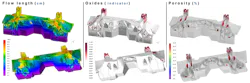
No tooling design exists at this early stage of development. The workflow uses only the CAD geometry of the cast part to analyze local thickness, thickness transition, sharp edges and draft angles. This provides a simplified filling-and-solidification simulation that identifies probable defect locations by pinpointing variables such as where flow length is excessive, where oxides are likely to accumulate and where porosity may concentrate.
It’s important to note that this is not a full process simulation; rather, it’s a castability screening step that uses part shape as the primary input. The results are directional, not precise, with the value in early risk identification at low computational cost, not in replacing detailed process modeling later.
Step 2: Mapping Defects to Local Material Properties
In this step, casting defect fields are mapped based on the simulations from the first phase. Material properties—particularly elongation—are modified locally using dependency relationships.
Modular material models split constitutive behavior into independent property blocks that can be driven by process-derived fields. This allows local mechanical properties, such as elongation, strength or failure strain, to be mapped as functions of casting-related fields including flow length, porosity, oxide content or thermal history, rather than the homogeneous-material assumption associated with traditional workflows.
During this phase, casting process data and structural analysis begin to share a common material model rather than existing in separate workflows.
Step 3: Crash with Manufacturing-Aware Data
After mapping material properties and defining their dependency results with casting simulation, performing crash simulation is the final step. Applying this mapped, non-homogeneous material model to a cast component within a full-vehicle crash model surfaces numerous insights not visible via traditional processes.
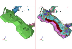
THe image below illustrates Hyundai’s crash comparison between homogeneous material case (left) and mapped material case (right). Looking at deformation specifically in the latter, there are two additional failure areas compared to the homogenous model. Areas of low dash intrusion (less than 20 mm) increased to 30-50 mm in the mapped material case. It is evident that the mapped material case provides more accurate crash modeling while the homogeneous model under-predicts risk.
This is not just a fidelity improvement—it changes what the engineer does next. Areas that looked safe under uniform assumptions may now require local reinforcement, geometry changes or adjustments to the casting process itself. Design choices that appeared validated require further review. The conversation between the structural and manufacturing teams starts earlier, with shared data rather than surprises later in the design process.
Trade-offs, Limitations and Broader Applicability
Simplified casting simulation is not a substitute for full process modeling. The approach enables structural and design engineers to balance computational effort against engineering insight, providing enough fidelity to change decisions at an early stage but not enough to replace a detailed process optimization in a subsequent phase.
One limitation of the methodology is that structural and design engineers must have enough casting knowledge to build realistic simulations and identify the most relevant risk areas. In practice, that means the approach works best when engineering teams have a working understanding of both casting behavior and the manufacturing variables that influence crash performance.
It is also important to note that the workflow adds simulation steps and requires collaboration between teams, necessitating that manufacturers adjust timelines and revamp workflows accordingly.
READ MORE: How AI and Software-Defined Design are Making Digital Twins More Accessible
As the automotive sector grows increasingly reliant on aluminum cast parts, moving beyond the homogeneous-material assumption is a critical step in reducing costly redesigns and ensuring passenger safety. The manufacturing variability in these components demands a modern, engineering-led workflow that integrates simplified casting simulations into early CAE.
With this approach, structural and design engineers can better predict failure modes and understand how components will withstand potential crash scenarios.
The automotive sector is not the only one that stands to benefit from this methodology. Any safety-critical structure made from cast aluminum or iron faces the same challenge, for example, aerospace brackets, heavy-equipment load frames and defense components. In industries where process variability affects structural integrity, the same methodology can theoretically be applied.
What Engineers Should Do Next
A critical consideration for individuals designing or analyzing cast structural components is to challenge the homogeneous-material assumption as early as possible. The sooner engineers incorporate manufacturing-aware material data into the design process, the better their crash prediction fidelity will be.
This proven methodology enables them to iteratively optimize part design and manufacturing conditions to meet structural performance requirements, resulting in stronger components with fewer late-stage surprises. What’s more, it’s achievable with current simulation tools and does not require the full manufacturing process data, so teams can integrate it into their existing workflows.
As automotive and other safety-critical manufacturers increasingly use cast components, understanding their structural behavior in crash scenarios early in the design process will be an essential step in preventing redesigns and minimizing recalls.
This article was contributed by Keysight Technologies subject matter experts, including Mathieu Moerckel, Application Engineer, Design Engineering Software; Yong-ha Han & Young-Tae Kim, Virtual Technology Innovation Research Lab / Hyundai, Korea; and Inhyeok Lee, Jangho Ahn & Junhyung Kim, Keysight Technologies, Korea.
More content from Special Focus: CAD/CAM/CAE.