

A servodrive only performs well when it is programmed in the units designated by its designer. The problem is that motor-datasheet units, definitions, and conversions vary by manufacturer.
There is no unified convention for publishing servomotor data. Nor is there a standard set of units or nomenclature for entering motor data into drives. So, it’s the job of the integrator to understand and homogenize parameters. This task is most critical when setting up servocontrol loops: Inaccuracies prevent servodrive control algorithms from acting properly and reacting to the ever-changing commands, loads, and feedback signals that characterize dynamic applications.
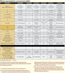
Why the inconsistencies? Many variations arose because there are two main electronic-control methods for permanent-magnet, three-phase synchronous servomotors: Sine-wave and six-step (trapezoidal) commutation. The Motor parameters conversion table in this article maps such instances and the varied parameters’ relationships.
Motor-name variations
Servomotors can be classified as brushless-dc motors (BDCMs or BLDCMs), servos, brushless-dc/ac synchronous servomotors, ac permanent-magnet (PM) servos, and more. Servo manufacturers established most of these terms in the 1980s for marketing purposes and to underscore that ac permanent-magnet (PM) motors (which are electronically commutated to create PMAC servos) can replace the servo function of permanent-magnet dc-brush motors.
Over the years, some industry sources invented explanations for the technologies’ varied naming conventions. Many such explanations relate to Bemf characteristics — clean sine-wave sinusoidal commutation or six-step or block commutation, also known as trapezoidal commutation, in which each electrical cycle (one electrical cycle or PM pole pair) is six commutation steps. However, the bottom line is that more than anything else, the conventions aimed to overcome false perceptions of technological barriers.
Regardless of their varied naming conventions, all of these motors are basically three-phase (Φ) ac-PM synchronous machines.
For the purpose of this article, consider a three-phase wye (Y)-connected motor capable of good three-phase sinusoidal-emf waveforms when backdriven as a generator, with electrically balanced windings, versus a delta (Δ)-wound armature.
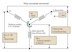
We use this example because most three-phase ac-PM servomotors today utilize wye-connected armatures, especially for sinusoidal commutation. (Consideration of torque angle advance algorithms and harmonic issues are beyond this article’s intent and scope.) Following is the commonly used nomenclature for such a motor.
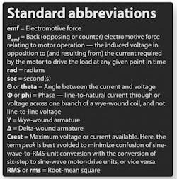
The emf-voltage constant
The voltage (emf) constant is usually abbreviated Ke, but sometimes appears as Kemf, KE, or Kb. It is the maximum line-to-line voltage developed per some velocity unit, such that when the velocity unit is rad/sec and Kt is in Nm/A, then Ke (V/rad/sec) = Kt (Nm/A). This is also true for PMDC brush servomotors, for which KE (Vdc/rad/sec) = Kt (Nm/Adc), with no consideration for the difference between motors that are cold (at ambient temperature) or hot (at the maximum or application operating temperature.)
Two widely used Ke units are V/rad/sec and V/Krpm:
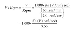
where V = Vdc bus for most drive systems = Maximum (crest) voltage available — Not in RMS terms.
Ke = Voltage (emf) constant, expressed in either
V/rad/sec, V/Krpm, or other equivalent — typically associated with six-step commutation (not sine-wave commutation).
For a wye-wound armature, if a motor data sheet defines the voltage (emf) constant as the phase (line-to-neutral) voltage developed per some velocity unit, it must be multiplied by √3 for a final result in the line-to-line Ke units defined above.
The Bemf voltage constant
The voltage Bemf constant Kb (also listed as KBemf, KB, and Ke) is the line-to-line RMS voltage developed per some velocity unit.
Kb (Vrms/Krpm) = Ke (V/Krpm)/√2, or
Kb (Vrms/rad/sec) = Ke (V/rad/sec)/√2
where Kb (Vrms/Krpm) = Ke (V/rad/sec) · 1,000/9.55/√2.
The voltage (Bemf) constant Kb expressed in
Vrms/rad/sec, Vrms/Krpm, or other equivalent is typically associated with sine-wave communication (not six-step commutation.)
If a motor data sheet defines the Voltage (Bemf) constant as the Φ (line-to-neutral) RMS voltage developed per some velocity unit, it must be multiplied by √3 for a final result in the line-to-line Kb units defined above.
The torque constant
The torque constant Kt (sometimes denoted KT) is the ratio of some torque T unit over either the maximum (crest) motor-phase current (line to neutral), or the RMS phase current (line to neutral).
Note that the two different specifications for the term Kt arise because of the differences between six-step and sine-wave commutation. These differences prevent many engineers from deducing the relationship between the two Kt current units.
Furthermore, it’s generally assumed that the torque constant is torque developed per some unit of current through one phase of the wye-wound armature. Therefore, manufacturers don’t always publish its exact definition in literature or motor-specification sheets.
In a wye-wound armature, line-to-line current is equal to line-to-neutral current.
- The torque constant Kt (sometimes KT) associated with six-step commutation is the ratio of some torque T to the maximum (crest) phase (Φ) current (line to neutral), where Kt is in the units T/A. For this definition and a three-phase servomotor, current flows through only two of the three motor coils (2-ON, 1-OFF) at a time.
- Torque constant Kt (sometimes KT) associated with sine-wave commutation is ratio of some torque T to the RMS phase (Φ) current (line to neutral), where Kt is in the units T/a-rms. For this definition and a three-phase servomotor, current may flow through all three coils at the same time.
When manufacturers publish the torque constant for sine-wave commutation in the units Nm/amp (crest of sine-wave) then:
T/a-rms = √2 · Nm/amp (crest of sine wave).
Conversion between the two commutation methods for the torque constant is:
Kt (Nm/A) = Kt (T/a-rms)/√1.5
and Kt (T/a-rms) = Kt (Nm/A) · √1.5.
Therefore, continuous current Ic (rms) required by a given motor to reach full capacity has a lower value than if presented as an Ic (crest or dc-style) current — just as one would expect.
We will not cover the formal derivation of √1.5 for converting between six-step and sine-wave commutation Kt and current. However, it’s verified by the equivalency of six-step and sine-wave power-loss calculations. See the Motor parameters conversion table:
Drive selection
Let us assume that we’re selecting a drive in the form of a sinusoidal-commutation controller requiring motor parameters in the following units:
- Continuous motor current units: a-rms — Ic (motor), RMS value of motor’s continuous capability per Φ (line-neutral).
- Peak motor-current-limit units: a-rms — Ip (motor) is the RMS value describing the motor limit per Φ (line-neutral)
- Kt constant units: Nm/a-rms — Torque_unit/a-rms for a sine-wave controller, with line-to-neutral (Φ) RMS current
- Kb constant units: Vrms/Krpm — RMS voltage line to line per 1,000_rpm
- Rm (typically 20 or 25°C room temperature) units: Ohms (Ω) line to line — Two phases in series, Rm_Φ = Rm (L-L)/2]
- L or Lm inductance (line to line), inductance units: milli-Henry or mH — L_Φ = Lm(L-L)/2
- Motor rotor inertia Jm units: Kg-cm2
Notes on common variations
Following are subscript notes for the Motor parameters conversion table.
- Most often the phase (Φ) current and (Φ) voltage (line to line) is defined somewhere in the manufacturer’s data. However, it commonly assumed to be understood.
- For a wye-wound winding, if a data sheet states Lm = LΦ (line to neutral), multiply LΦ by two for the total motor inductance Lm (in mH, line to line).
- For a wye-wound winding, if a data sheet states Rm = RΦ (line to neutral), multiply RΦ by two for the total resistance Rm (line to line). For a delta-wound motor, resistance (Ω) is Rm/Φ = Rm (line to line).
- As temperature climbs from 25° ambient to a maximum of 155°C, resistance of the copper increases by a factor of approximately 1.525.
- For a given motor and the scope of this article, when power for six-step commutation is set equal to the power for sine-wave commutation:
2 · V_Φ · I_Φ · cosΘ = 3 · V_Φ · I_Φ · cosΘ
The cosΘ factors out of the equation. - Conventional three-phase trapezoidal commutation drives control only two motor windings at a time. Sinusoidal commutation drives can concurrently control all three windings.
- For sine-wave commutation (Column F in the Motor parameters conversion table) if a drive demands that Ic (continuous) and Ip (Ipeak) be entered in the units:
Ic (crest of the sine wave)/phase (Φ)
Ip (crest of the sine wave)/phase (Φ)
Then the corresponding value in Column F must be multiplied by √2.
If the specific parameters are to be entered in the units:
Ic (crest to crest of the sine wave)/phase (Φ)
Ip (crest to crest of the sine wave)/phase (Φ)
Then the corresponding value in Column F must be multiplied by 2 · √2.
Note that “crest” is used here to minimize confusion of the myriad terms for peak motor and drive capabilities with expressions relating to sine-wave peak (crest) or peak-to-peak (crest-to-crest) values.
The Motor parameters conversion table can be also be used as a quick-check nomenclature reference. For example, to verify that Kt and Kb (or Ke) are in RMS units, divide what is thought to be Kb (Vrms/Krpm) by Kt (Nm/a-rms). If the corresponding units are correct, the resulting quotient will equal some quantity between 60 and 65, or (in a few exceptions for rounding off) just over or under that range. The method typically works regardless of the assumed motor temperature (operating or ambient) or PM servo type.
Also visit kollmorgen.com or email [email protected].
About the Author
Voice Your Opinion!
To join the conversation, and become an exclusive member of Machine Design, create an account today!

Leaders relevant to this article: