Modeling Machine Designs that Seal Deals
Key Highlights:
- Modeling and simulation provide engineers with insights that are difficult or impossible to obtain through physical testing alone, leading to better optimized designs.
- Moog utilizes tools like Simulink, MATLAB, and its proprietary MAST library to analyze and validate complex hydraulic and motion control systems across various industries.
- Early digital validation helps identify potential flaws, reduce development costs and shorten time-to-market for innovative products such as hypercars and large forge presses.

Enjoying Machine Design’s Industrial Equipment & Heavy Machinery content? Be sure to check out the rest of our Takeover Week coverage here.
Modeling and simulation run like a thread through the fabric of technology for industrial applications. Whether the designs are novel or extreme, modeling provides design engineers and their customers with answers that may be hard or impossible to get another way.
“Before modeling as we now know it, there was Fortran in the 1970s,” says Ian Whiting, UK-based chief engineer for Moog, a designer, manufacturer and systems integrator of high-performance motion control systems. “But Fortran was for universities and just too time-consuming for applications work.”
Since Moog’s founding in 1951, designing high-performance motion control products like hydraulic servo valves has been a focus for the company. Moog’s design engineers have gone from creating and relying on technical know-how bulletins for insight to building powerful simulation and analysis tools. Whiting says simulation and modeling today at Moog includes Simulink, MATLAB, and Moog’s proprietary product and system engineering simulation library called MAST, or Moog Analysis and Simulation Toolbox.

What is the Value of Modeling and Simulation for Machine Design?
Beyond physical prototyping, design engineers use system-level models to simulate, analyze and optimize mechanical and electrical solutions. Early validation can detect design flaws and reduce risk, while helping to convince a customer of an engineering workflow that they may not have considered.
“A digital simulation can save thousands to millions of dollars,” adds Whiting. “Whether that’s compressing design time or avoiding a flawed solution.”
Modeling and simulation can optimize designs across multiple disciplines, such as mechanics, hydraulics, sensors, electronics and software. That said, Whiting and his colleagues’ focus has been on modeling servo hydraulics, a special-yet-quite-diverse niche.
According to Whiting, there are more control-related challenges with hydraulic solutions than electric. And the solutions with servo hydraulics are not so obvious. Modeling offers an effective way to design for an application. For example, if you are driving an axis with a ball screw, it is very stiff. If you drive it with a hydraulic servo, the oil stiffness is not necessarily high or even consistently stiff.
READ MORE: MBSE Gains Ground in Heavy Equipment Industry
Machine dynamics become important when sizing servo hydraulics technology. The modeling tools for this work include using Simulink supported by MAST, says Whiting. The work isn’t just about modeling static force and speed; it is also about the control of dynamics.
“Hydraulic sizing is something that's been done since the beginning of time,” says Whiting. “You could find technical know-how bulletins in our files that Bill Moog and his associates developed with rules of thumb to compare and set stiffness and frequencies for servo hydraulics.”
But with modeling, Whiting says an engineer can observe the problems that arise when driving a system much harder than what is normally considered practical. They can then come up with solutions before production.
For instance, using digital technology for closed loop control, microprocessors gives engineers more flexibility in algorithms than with old analog electronics. Today’s modeling tools help engineers deliver more complex solutions while the analysis tools provide a way to get more performance from a smaller package (e.g., power density for hydraulics can be higher than in the past).
There are cost savings that come from using modeling to create and present designs more easily. But the real power of simulation, says Whiting, is using it to convince a customer from the get-go that your design is better than anyone else’s. Simulation tools can show what an engineer would measure while analyzing a real machine. An engineer can examine variables deep inside the machine that are not, say, manifold or pipeline pressure fluctuations or unwanted load reaction displacements in a motion control system.

Modeling and Simulation in Practice: From Wimbledon to a 50,000-tonne Forge
Moog has relied on simulation and modeling for designing the electric roofs over Wimbledon’s Centre and Number One Courts, mini hydraulic actuation for a Hypercar, and hydraulic system design for one of the world’s largest forge press machines.
According to Whiting, sometimes simulation can find and illustrate technical problems with a customer’s requirement that invites a discussion. The simulation might show how much harder creating the solution is than the customer envisions.
Take the Wimbledon roof; each roof truss would ultimately span about 75 meters with structural resonances starting off at around 1Hz due to the distribution of mass and stiffness. Moog’s digital simulations showed the project team several models for how out of shape the motion control of the trusses could get—ultimately damaging the roof because of the massive amount of force.
System level models are normally digital, which for Whiting means “a digital model that you run offline on a PC or computer.” He adds, “For the Wimbledon roofs, there was also a physical realization of at least part of the system.”
The offline analysis showed there would have been too much risk to rely solely on digital computer modeling. So, the project partners led by Moog settled on a “full-scale model,” of a portion of the roof, including a reduced number of trusses to validate the actuation concepts including axis interaction. Wimbledon accepted Moog’s analysis and risk mitigation proposal.
Moog then constructed a physical test rig in the north of England at a mothballed steel mill to validate the modelled solutions, test algorithms, make decisions and get sign-off on the final design. Part of the modeling relied on the MAST library of reusable modelling assets (e.g., controllers, servo valves, actuators), and in this case electric motors, gearboxes and balls screws.
With the one-two punch of the modeling and a physical test system, Moog proved the roof would work. Wimbledon agreed and ultimately completed construction on the first roof over Centre Court in 2009, followed by a second roof over No. 1 court in 2019.
By way of background, Moog developed its assets in MAST over years to analyze electric drive and servo hydraulic motion control systems. By the time MathWorks developed hydraulic capabilities as a standard tool, says Whiting, Moog had already established MAST.
“The systematic characterization of Moog products is an essential aspect of MAST that continues to serve us well to this day” says Whiting.
Pumping up Performance, not Cost
Moog’s engineers have also applied simulation in the design of high-performance hydraulic automotive motion control systems. Moog’s E024 Series servo valves designed for F1 applications switch at up to 350 Hz—roughly 300 times per second—with a response time of about 1.5 milliseconds.
When Moog got a call from a luxury brand to adapt F1 fly-by-wire actuation technology to a street-legal Hypercar, the challenge was balancing cost, size and performance for the vehicle developer. Hypercars often come with a price tag of $750,000 and higher.
READ MORE: COMSOL 2025 Highlights Real-World Multiphysics Applications
“It was a modeling exercise to come up with a servo valve with F1 characteristics but not truly the same valve; the simulation was really a sort of due process,” recalls Whiting. “We could make a less costly servo valve work but weren’t sure about the implications for actuation dynamic and static performance. So, modeling created different workflows to see what we could achieve and the effect on the car’s existing components.”
In the MAST, Moog put its new servo valve into a closed loop system, including sensors to send signals from the driver’s command into the Hypercar’s controller that delivers an output to the vehicle’s actuating devices and back again. The engineers simulated how friction, seal design and actuator sizing would affect the servo valve’s required performance.
The simulations helped the Hypercar maker modify its mechanical design and sealing to achieve performance while meeting the application’s footprint and costs. Modeling helped win the Hypercar business for Moog, allowing the car maker to make good design decisions from the start.
Pressing Forward with Simulation
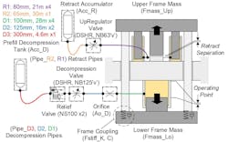
Modeling also played a key role in winning an order to provide valve gear and manifolding for a 50,000-tonne forge press. To achieve such massive die-forging loads at speed, the press’ system return requires the rapid decompression of hydraulic fluid.
Accelerating fluid at low pressure into the press’ return system could have caused significant pipeline damage from cavitation and fluid inertia. These factors are especially difficult to manage for larger pipelines (e.g., up to 300 mm diameter and 50m in length), the type found on the press.
The press maker tapped Moog for help because of the New York-based firm’s range of solutions. For instance, Moog’s work in motorsports can require a servo valve flow rate as low as 0.5 liters per minute; the valves Moog ultimately used for the press had a flow rate of 40,000 liters per minute.
Among the first steps Moog took to solve the press maker’s challenge was using Simulink and MAST. The engineering team modeled the decompression process including the return system physical layout, valve type and algorithms to safely decompress hydraulic fluid in this extreme application.

Simulation the Moog Way
In each example above, the engineering team’s approach was similar in that they took a given analytical study through a sequence of events. Whiting says this mirrors how Moog continues to simulate and model solutions. Its engineers begin with a customer’s stated requirements and problem. They assess the risks. And then the engineers tackle basic sizing to establish the extent of their investigation.
The team assesses model fidelity requirements and appropriate models drawn from the MAST libraries. For example, the valve models may be sufficient in simple blackbox form described by 10 or less parameters, or the team may need to construct full physical models requiring around 60 parameters. Moog’s engineers would then define actuation and sensor options to fit with the mechanical layout of a customer’s machine, so they can compare potential solutions and select the best options.
“Making good algorithmic choices for the servo controller design and properly representing the effects of sampling and quantization is an essential step towards the end of the workflow process,” notes Whiting. “Whilst the power and capability of modern digital control systems is widely exploited, we give all aspects of the servo system equal weight.”
READ MORE: Simpler, Smaller and Smarter: Simulation Tactics for Better Product Design
That means representing the interacting elements of mechanics, actuation, sensors, controllers, electronics and software. The easy connectivity of those MAST elements in the Simulink modeling environment is a key part of an efficient and robust process that Moog relies on.
“MAST has become the bedrock of our simulation work because if we were to buy a general-purpose simulation tool, it wouldn’t have any of the Moog-specific technology,” remarks Whiting. “We would have to recreate elements, and the functions underneath are not necessarily the ones we would like.”
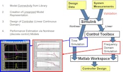
According to Whiting, Moog sometimes undertakes simulations as a paid consulting engagement. In these cases, the process is essentially the same as the Wimbledon and Hypercar work detailed above; a customer supplies Moog with its application challenges and any design data as inputs. As with the Wimbledon roofs, Moog would build a customized model from the customer’s system measurements and design data by going into Simulink and MAST.
Whiting and his team would simulate non-linear and linear models with idealized physics. Then engineers determine the algorithms in principle and test for friction and backlash. They would then deliver the developed models along with a report outlining any issues and demonstrating the expected machine performance.
“Those reports show a customer the kind of results we can deliver if we’re to apply our technology to solve their problem,” says Whiting.
And, often, that kind of modeling has sealed deals for Whiting when it comes to machine design.
About the Author
Bill Perry
Bill Perry is a freelance writer based in Upstate New York who has written about manufacturing, utilities construction and software for 30 years.
Voice Your Opinion!
To join the conversation, and become an exclusive member of Machine Design, create an account today!

Leaders relevant to this article: