CNC Guide (Part 2): How Changing Features Can Mitigate Manufacturability
Editor's Note: An updated version of this information can be found here.
A part’s features sometimes make it more difficult to manufacture, or can increase cost and time. Understanding what affects the difficulty, time consumed, and/or cost of a part that needs to be machined is important. The following presents tips on designing parts for manufacturability with vertical milling machines, horizontal milling machines, and lathes. For more information, check out Part 1 of this guide.
Interior Fillets
When using a CNC vertical or horizontal milling machine, all interior vertical walls must have a radius. That’s because a round tool, spinning at high RPMs, is used to remove the material. Designs must take into account areas where radii will occur due to this limitation.
Inside Corner Fillets
For inside corner radii, it may be better to use a non-standard radius. This is because end mills need clearance to turn and continue milling when tracing the internal corner. If a part features a 0.25-in. interior radius, the standard end mill would need to hammer the corner, come to a complete stop, pivot 90 degrees, and then resume cutting. Doing this slows down machining speed, which adds costs and causes vibration. By adding 0.02 in. (0.508 mm) to 0.05 (1.27 mm) in. to internal radii, the cutter will be able to turn slightly without coming to a complete stop. This will not only reduce cost, but also improve CNC parts.
The larger the radius, the lower the cost. The reason for that is a larger tool can be used, which means more material can be removed with each cut, thus reducing the time to machine the part. For example, a tool with a 0.125-in. diameter (0.063-in. radius) would take approximately 1.5 times longer to perform the task than using a 0.187-in. diameter tool, and approximately two times longer than a 0.250-in. diameter tool.
Even though small-radius tools (down to a 0.015-in. radius) are available, sometimes the depth that the tool needs to go into the material makes it impossible to cut because the tool is not manufactured. If the tool is manufactured, the cost will increase significantly due to the fact that only small cuts can be made, which extends the manufacturing time.
When the depth of cut becomes greater than two times the diameter of the cutting tool, then the feed rate of the tool will need to be slowed down, leading to increased cycle time and costs. For every doubling of the depth of cut, the feed rate is more than halved, which more than doubles the time to cut the feature. The max cut depth to tool diameter ratio is six times; beyond that, special tooling will need to be ordered. For example, if a 0.125-in diameter tool is used, then the max cut depth would be 0.750 in. before having to use a custom tool.
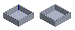
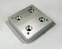
Vertical, interior wall features are impossible to create with a round tool (left). All vertical, interior wall features must have a radius (right).
Floor Fillets
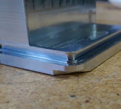
When creating a floor radius that meets to a corner, it’s much easier to machine if the floor radius remains smaller than the corner radius. With modern CAD systems, it is simple for the designer to just click and have the computer generate the same size floor and wall radius. However, this makes it very difficult to remove the material in the corner. By having the floor radius smaller than the vertical wall radius, the same tool can be used to remove the material and create a smooth flow through the corner.
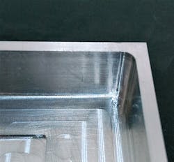
Machined wall fillet
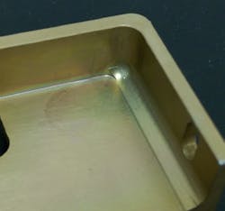
Machined floor fillet
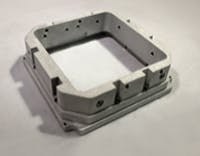
Undercuts
During the design process, sometimes features are created where a standard machining tool cannot reach the area, thus creating an undercut region on the part.
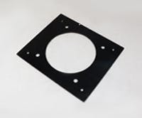
Care must be taken when designing an undercut, for a couple of reasons. First, the undercut may require the creation of a special tool if the feature is not a standard dimension. In the example below, the radius in the slot is 0.053 in. A costly custom tool would be required to create the geometry, which would significantly increase the part’s cost, especially if only a few parts are to be manufactured. If a standard 0.062-in. radius is used, then the cost of the tool would be less than half the custom tool’s cost.
The second reason to be careful when designing undercuts is to make sure the undercut is not too deep or cannot be reached. Since the required tool has a horizontal cutting blade attached to a vertical shaft, it limits the depth of the cut. There is no hard and fast rule as to the depth of the undercut, but the shallower it is, the better. Also, when designing the undercut feature, it is critical to only create undercuts in areas that can be reached by the tool. The illustration below depicts an undercut feature that cannot be reached in the machining process.
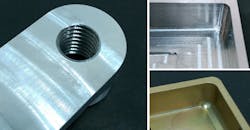
Threads
There are several ways to create threads in a part: cut taps, form taps, or thread mills. All of these methods are effective, but the design engineer should keep a few things in mind.
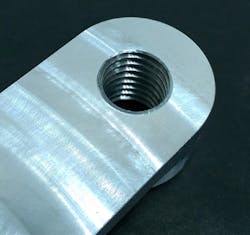
Always choose the largest thread size possible allowed by the design, because it facilitates the manufacturing process. The smaller the tap, the greater the chance that the tap will break during production. Only thread to the length necessary. Deep, threaded holes can increase the cost of the part, because specialized tooling may be needed to meet the depth requirements. Try to use off-the-shelf thread sizes to save on costs. Be sure to add threads to quotes, and attach a specified drawing, or else parts will be machined to the specified diameter.
Surface Finish
Xometry offers a wide variety of finishes based on the needs of the customer.
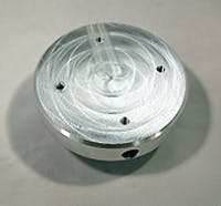
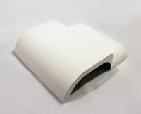
Standard, As Milled Finish
This finish is equivalent to a 125 RMS finish, where minor tool marks will be visible on the part. Increasing the surface-finish requirements to a 63, 32, or 16 finish can increase cost because feed rates might need to be reduced and/or additional post-processing may be required to create the desired finish.
As milled – 63 finish.
Bead-Blast Finish
A light texture with a matte finish is created by blowing small glass beads against the part in designated areas. Additional cost may be incurred if the design requires significant masking of surfaces or holes that do not need the bead blasting.
Anodizing, Type II
This type creates a corrosion-resistant finish. Parts can be anodized in different colors—clear, black, red, or gold are most common—and is usually associated with aluminum. See MIL-A-8625A for additional information on anodizing.
Anodizing, Type III (hard anodizing)
This type is thicker and creates a wear-resistant layer, as well as the corrosion resistance seen with Type II. See MIL- A8625A for additional information on anodizing.
Powder-Coat Finish
In this process, powdered paint is sprayed onto a part and then sent through an oven to bake the paint onto the part. This creates a strong, wear- and corrosion-resistant layer that is more durable than standard painting methods. A wide variety of colors are available to create the desired aesthetic look for the part.
Other types of finishes are available, such as chemical film conversion or plating. This article only covers a few of the more common finishes. Such features and finishes can greatly affect the cost and time to make a part, which will help your product stay competitive in the market.

About the Author
Voice Your Opinion!
To join the conversation, and become an exclusive member of Machine Design, create an account today!

Leaders relevant to this article: