Worm Gear Reducer Efficiency: Ratio, Run-In and Input Speed

Worm gear reducers play a key role in mechanical systems due to their ability to achieve high gear reduction in a simple, compact design. This unique functionality makes them suitable for a range of applications, including hoists, conveyors and various machinery drives.
Worm gear reducers are “right-angle” reducers because their input shaft is oriented 90 deg. from the output shaft. This arrangement allows for a cost-effective, simple design that is quiet, rugged, shock-resistant and allows for compact conveyor and machinery arrangements.
Other commonly used right-angle gear reducers include but are not limited to helical-bevel, helical-hypoid and helical-worm reducers. Each type of reducer has a unique set of characteristics, which are discussed here.
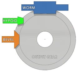
There are different physical arrangements between bevel, hypoid and worm gears, as seen in Figure 1. In bevel gears, the axis of the input pinion intersects the axis of the output gear. This is not the case with hypoid and worm gears.
Due to this off-set arrangement, the sliding action within the gear mesh is higher with hypoid gears than bevel gears and higher again with worm gears. This increased sliding results in greater frictional losses and the requirement for special lubricants specifically designed for hypoid and/or worm gears.
Reducer Efficiency and Gear Reduction Ratio
Gear reducer efficiency has always been and continues to be a primary consideration for designers in the power transmission industry. It’s important to understand that different types and ratios of right-angle gear reducers can yield significantly different levels of efficiency.
The helical-bevel arrangement typically uses one or two helical gear stages mated with a bevel gear stage to “turn the corner.” These reducers have the distinct advantage of high efficiency, which is independent of the reduction ratio and run-in time. This benefit typically comes at a higher cost due to more complicated gear design and larger number of components.
The helical-hypoid gearing offers an alternate physical arrangement if needed and is similar to the helical-bevel; however, it has a slightly lower efficiency due to the additional sliding action associated with the hypoid gear stage. Cost and complexity of this arrangement is like that of the helical-bevel design.
Worm Gear Reducer Efficiency and Reduction Ratio
Several factors influence the overall efficiency of a worm gear reducer. These factors include the geometry of the gear teeth, the materials used for the gears, the selection of bearings, the level of load applied, the type and viscosity of lubrication, the run-in condition of the gear flanks, the input speed, the reduction ratio, settings for bearing endplay and pre-load, oil seal drag, oil churning through the gears and bearings, and the operating temperature.
The Dudley Gear Handbook provides formulas to compare and estimate worm gear efficiencies. These formulas provide theoretical estimates only. Actual testing of a run-in and loaded gear set is necessary if detailed efficiency information is required for a particular gear set.
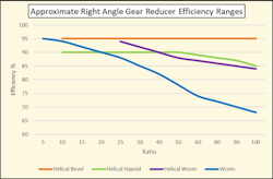
Ratio impact. In the case of worm gears, common ratios range from 5:1 to 100:1 in a single stage. In worm gears, the efficiency varies inversely with respect to the gear ratio. In other words, as the reduction ratio increases, the efficiency decreases. Reference the blue line in Figure 2.
Worm gearing is often associated with lower efficiency; however, there are two areas in Figure 2 worth noting. The data shows that in ratios of 20:1 or less, efficiencies of 90% or more can be achieved with a worm gear after run-in. Also, in helical-worm arrangements, efficiencies of 90% or greater can be achieved in ratios of 25:1 to 40:1.
These higher efficiencies at low ratios are a result of the higher lead angle used for low ratio worm gears. The lead angle of typical worm gear geometry usually varies between 2 and 40 deg. As the ratio is increased, the lead angle must be reduced, resulting in greater sliding action between the worm threads and gear flanks.
A helical-worm arrangement achieves its efficiencies by taking advantage of the high efficiency associated with helical gearing combined with the high efficiency of low ratio worm gearing to arrive at a middle ground efficiency between single reduction worm and helical-bevel.
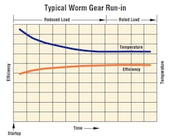
Run-in. Typical worm gear reducers use a hardened steel worm driving a bronze worm gear. The efficiency of a new worm gear reducer is often less than a well-run-in reducer due in part to the fact that the gear teeth on a new worm gear are not smooth. They will have small hobbing facets on the flanks of the bronze gear teeth. The edges of these facets are high spots that can interfere with the generation of a hydrodynamic lubrication layer when the worm is spinning at the typical 1,750 rpm. A run-in period of 10 to 100 hours is typical for worm gears. During this time, the efficiency increases, and sump temperature decreases as the facets are worn smooth and “work hardening” occurs on the bronze flanks resulting in a more effective hydrodynamic lubrication film.
Self-locking and back driving. Worm gears are often utilized in applications due to their resistance to back driving. As a worm gear set runs-in and its efficiency improves, its tendency for back driving also increases. There have been many occasions where a worm reducer does not back-drive when new and then begins to back-drive after some time in operation. If an application cannot tolerate back-driving when stopped, a brake is often the best option.
Input speed. Input speed has a significant impact on worm gear efficiency as well. With typical motor input speeds of about 1750 rpm, a hydrodynamic film is present which helps increase efficiency. At start-up and low input speeds, metal to metal contact and/or boundary layer lubrication conditions are present which will result in lower efficiency. Start-up efficiency losses can be significant and in the range of 30 percentage points lower than full speed loaded operation.
Lubrication. Modern worm gear reducers offer the best efficiency when utilizing synthetic PAG (Polyalkylene Glycol) lubricants. PAG lubricants are hydrophilic and can be problematic if water enters the reducer. Synthetic PAO (Polyalphaolefin) lubricants offer efficiencies nearly as high as PAG and offer better tolerance for water ingress.
In conclusion, worm gear reducers are vital components in the power transmission industry, offering a compact, rugged and reliable solution to achieve gear reductions in mechanical applications. While worm gears are often associated with lower efficiency compared to other right-angle gear types, understanding the factors that influence their performance will lead to more cost effective and efficient designs.
About the Author
Rob Holdsworth
Manager of Engineering, Peerless Winsmith, Inc.
Rob Holdsworth is the manager of engineering at Peerless Winsmith, Inc. He has been with Winsmith for the past 17 years and has more than 30 years of experience in the automation and power transmission industries.
Voice Your Opinion!
To join the conversation, and become an exclusive member of Machine Design, create an account today!

Leaders relevant to this article: