How Brakes Make or Break Medical (and Other) Robots
Key Highlights
- Use pneumatic and hydraulic brakes where high torque density is needed and support systems like compressors can be tolerated
- Use electroadhesive options when space is limited and controllable torque limits are desired
- Use electroadhesives when weight, heat, or power reduction is the main goal and pneumatics and hydraulics can’t be supported
- Use magnetic solutions when heat, space and EMI is not an issue and cost is the biggest factor
- Use magnetic, hydraulic or pneumatic failsafe brakes when brakes need to remain engaged indefinitely
- Traditional magnetic, hydraulic and pneumatic brakes are often passed up in medical applications due to mass, weight, heat and complexity issues. Electroadhesive options fit where other solutions don’t and can open up new uses for brakes.
Enjoying Machine Design’s Motion Systems content? Be sure to check out the rest of our Takeover Week coverage here.
Safer, smaller, cheaper and power saving. These are the high-level performance metrics that are decision points for robotics customers. Pushing the boundaries on these key metrics is essential for expanding market share and ensuring professional growth. Brake selection can make or break success when size and cost determine which system becomes the leading standard. Lessons from medical robot design can be applied to all robotics from cobots to humanoids and autonomous mobile robots (AMRs).
Medical robots offer improved outcomes for patients, surgeons and hospitals, but their adoption rate is limited by price and size which are inextricably intertwined. Size drives costs and limits which hospitals can feasibly deploy surgical robots. These systems are so large that they can overcrowd an operating room, limiting bedside staff’s access to the patient. Additionally, not all operating rooms can fit bulky robotic systems. In fact, sometimes modifications to the building itself are necessary to accommodate their footprint.
Understanding why robotic surgical systems are so large requires an understanding of the requirements that surround them.
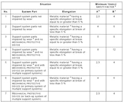
IEC 60601 section 9.8 Table 21 is one of the most referenced tables for medical robot designers. This table defines tensile safety factors that must be incorporated into medical equipment. Let’s look at this table and work through an example to understand how a robotic system designed to apply less than five pounds of force to a patient can rapidly grow into a giant.
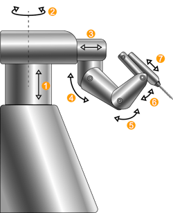
Take this simplified cartoon example of a medical robot with 6 degrees of freedom. The first three joints are gantry joints that are stationary while the system is operating. These typically only move at the beginning and end of an operation for setup and tear down. Joints 4, 5 and 6 are rotary joints that manipulate the orientation of the end effector during operation. Lastly, the 7th axis is linear and controls the depth of a drill.
If your goal is to reduce the weight of your system, start your work at the most distal joint (near the end effector), joint 7 in our example. This joint could be driven by a lead screw or belt drive. Belt drives are common in medical systems as they allow heavy actuators to be located more proximal to the robot’s body. This keeps the arms and end effectors of these systems slimmer and lighter which creates more space around the patient.
Let’s reference the table to determine the factor of safety required for a belt-driven linear axis at the end of a surgical robot’s arm. The belt is a “support system part impaired by wear” and in this example, there is “no mechanical protective device” such as a brake. The designer didn’t include a brake because there simply are no linear brakes small enough to operate in this joint. Let’s assume the belt is ductile and experiences elongation of more than 5% at break. This scenario places us in row 3 of Table 1. If we don’t have the dynamic loading of the system well defined, we have to look at column B for the minimum acceptable tensile safety factor. This requires our belt to have a factor of safety (FOS) of 8.
This FOS directly translates into weight because the best way to improve the FOS of a belt is to increase its width. A wider belt requires wider pulleys, requiring wider robotic linkages, wider housings and so on. Weight is typically proportional to width. The path to dramatically reducing the weight of a medical robot is through reducing the FOS required for belts and other drive and support structures.
Including an emergency brake halves the FOS required for the belt system. A brake is a “mechanical protective device” which shifts our cell from row 3 to row 5 and reduces the FOS from 8 to 4! This often translates to a linkage that is half as wide and therefore half as heavy. (Stick with this article to the end to see how brakes can further reduce the required FOS to 2.5)
Adding a brake to a belt-driven drive can reduce the weight of a link dramatically, and the weight of a multi-degree of freedom system exponentially. Surgical systems, cobots and industrial arms all suffer from the same pain point: leverage. The weight of end effectors and distal links act across great leverage and as such, require large, heavy structures at the base to support them. Larger tools require a larger wrist, larger wrist requires a larger elbow, a larger elbow requires a larger shoulder, and so on and so forth.
Each of these structures can have substantial required factors of safety further ballooning their size. This is how a surgical system designed to apply less than 5 lb of force can end up weighing 1,000 lb! Reducing the weight of the most distal joints can have dramatic cascading effects along the arm all the way to the base of the robot. Meaning small savings near the end add up to huge savings overall.
When Should You Include a Brake?
The FOS is tied to mass and overall envelope. In general, if your emergency brake weighs less than the mass that must be gained to double the FOS of your system, it is beneficial to adopt a brake. While it is straightforward to think about the weight savings for the braked joint alone, the designer must consider the cascading effects on components more proximal to the base. This is a lengthy exercise, but one well worth the effort.
Once the weight savings are estimated, the developer must keep in mind the following “ifs” that should be also be considered:
Adopt a brake if the following is true:
- The brake is lighter than the weight saved in the rest of the system by reducing the required FOS
- The brake doesn’t present a heat risk
- The brake doesn’t introduce unacceptable EMI
- The brake doesn’t impede the range of motion of the robot by adding bulk.
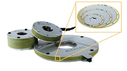
Electroadhesive brakes are a new type of robotic brake that addresses each of these “ifs” well. Electroadhesive brakes are the lightest electrically controllable brakes available. Electroadhesive brakes act like an electric glue. Instead of clamping and releasing a rotor, they stick and unstick to the rotor using static voltage fields. In other words, they lock and unlock using 1,000× less power than magnetic options with components that can be paper-thin.
They are exceptionally well-suited to the task of providing redundant safety for enabling weight reduction due to their small size, negligible power consumption, cool-to-the-touch operation and are magnetically transparent (no ferrous materials and negligible EMI). These brakes are made of modules that are 0.8 mm thick. A brake may consist of only one module, or modules may be stacked to increase holding torque linearly.
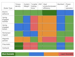
To help with brake selection, Table 2 summarizes the pros and cons of a few different brake options. It is included to show how electroadhesive brakes stack up against the most common conventional brakes.
In terms of torque density, electroadhesives are competitive with or outperform magnetic friction brakes. Electroadhesive brakes are incredibly lightweight. While pneumatic and hydraulic brakes typically outperform electroadhesive brakes in terms of torque density for high torque applications, they come with the added complexity of compressors, lines and reservoirs, which are not suited to many medical and most mobile applications due to size and noise.
Rotary electroadhesive brakes can be as thin as 0.8 mm and can be up to 10× lighter than conventional options. Electroadhesive linear brakes are even more compact and can be as thin as two pieces of paper (less than 0.35 mm) and weigh mere grams. While these brakes have exceptionally high force density, their holding force is determined by surface area.
This requires a significant footprint to generate large forces. Typical holding force is 1-3 N of force per each square centimeter of footprint between the moving and stationary sides of the brake. The total holding force is dependent on the geometry of the brake and the quality of alignment.
UltraSlim linear brakes can be particularly effective for providing redundancy for linear axes (joints 1, 2 and 7, in our example) as they act directly on the moving load. This means that they count as an emergency brake and will provide protection in the event of a broken ballscrew or belt.
Linear electroadhesive brakes have relatively low holding force compared to magnetic or pneumatic options but fit in spaces that a traditional brake simply cannot. For miniature linear systems there are no other electrically controllable linear brakes on the market. Due to their exceptional thinness, they can be retrofitted to existing systems with little to no redesign.
UltraSlim electroadhesive brakes can enable designers to put brakes almost anywhere. If two pieces of paper fit between the sliding components, an ultraslim brake will fit. While joint 7 is small, joints 1 and 2 feature large flat surfaces on the telescoping elements. These huge surfaces are ready to be wall-papered with ultraslim brakes.
Electroadhesives can turn housings and shells into braking surfaces. They can be used to enhance gravity compensation, provide controllable stiffness across a joint or to act as an emergency brake. Designers are encouraged to get creative and utilize any parallel, flat surfaces for mounting these brakes.
What Brakes Should be Used for Gantry?
Gantry joints only move occasionally. Using their motors to hold position is a waste of energy and generates a lot of heat. A brake is a much more efficient way to hold position and enables motors to be used at their peak torque rather than continuous torque which reduces the cost of the actuator.
The brake only needs to be energized for a moment to unlock it, motors move the gantry into place and then the brake reengages when power is removed. Using a brake instead of the motor for holding saves power, reduces heat production and prevents collapse in case of a power failure.
Common gantry brakes are electromagnetic power-off (AKA fail-safe) brakes. Mayr, Ogura, KEB, and Sepac are all great suppliers of these types of brakes. Springs force these brakes closed when power is removed. To open them power has to be applied to their coil to generate a magnetic field to draw the brake open.
These brakes can burn 10-40 watts of power to stay open so they work best on joints that don’t move frequently. It wastes power and generates heat to power both a brake and a motor simultaneously. Toothed magnetic brakes can be excellent options in gantry as they have higher holding torque and are less expensive than permanent magnet brakes.
An electroadhesive brake can perform the same gantry locking operation with a lighter, more compact envelope, but there is one significant drawback: Electroadhesive brakes engage when power is applied. They consume a nearly negligible quantity of power and can be operated on a small backup battery for hours, days or even weeks as emergency brakes.
When there is a need for a brake to be engaged indefinitely, electroadhesives are not recommended. For medical systems experiencing a power outage, a 24-hour backup battery is more than enough to hold the brake locked until the end of surgery at which point the system can be stowed. While this works well for some systems, it is certainly not the right solution for all systems.
Heat is a particularly challenging issue for surgical robots that can be mitigated by the use of cool-operating brakes. Medical robots often operate under a sterile drape, which makes cooling difficult. To make matters worse, any components of a medical robot that can come in contact with a patient must be less than 43°C if it is possible that an unconscious patient could be in contact for several minutes.
This requirement can be fairly limiting as 43°C is just not that hot. For reference, a cup of coffee is typically served between 49°C and 60°C. You don’t think of the cup of coffee as dangerous because you will switch hands or set the cup down once it causes discomfort. But an unconscious patient cannot move away and a burn injury can slowly develop. Electroadhesive brakes are always cool operating as only microamps of current flow through them to activate.
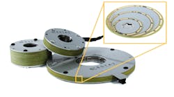
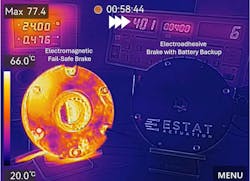
Joints 4, 5 and 6 may not need a brake if they are non-backdrivable, but any direct drive on these joints will require a brake. Since these joints are not gantry, they move frequently. An electromagnetic brake such as the one shown in figure 4 will add heat to the system while the motors operate the joint. An electroadhesive brake can be a great solution for these joints.
Electroadhesive brakes that fit into small spaces may be used to cut down on the heat produced by motors performing holding tasks. Brakes are not typically used for tasks like retraction (holding organs or tissue out of the way) during surgery as the motors that control end effectors move frequently. This means that the energy saved by using a brake is minimal and the energy consumed by the electromagnetic brake to remain open only adds to heat production and power consumption.
In general, motors are used for holding tasks in these joints because a brake typically only represents added weight and heat and the benefits of added safety are minimal. Electroadhesive brakes offer the first good brake solution in this scenario, as they are compact, lightweight and generate no heat during use.
Beyond simple holding tasks there are other great uses for brakes in medical robots: limiting torque and shock-loading protection. (I promised I would show you how to drive your required FOS down even further.)
Let’s say your robot hits the door jam while being wheeled into the operating room. Did you plan for this? If not, the load is transmitted up the arm to the elbow or shoulder’s harmonic drive, which breaks rendering the system unusable. To mitigate this, a torque limiting clutch can be placed in series with the gearbox output.
In the event that a shock load pushes torque above the allowable threshold the clutch slips and decouples the drive from the arm. The clutch simply reengages after enabling the slip. This is another clever way to reduce the required factor of safety.
When the dynamic loading is well characterized, the required factor of safety can be reduced from column B to column A in Table 1. In our belt example, our required factor of safety drops to 2.5. If the weight of this joint is proportional to belt width we have now reduced the weight of this joint by 68%.
As an added bonus, electronically tunable brakes can enable emergency egress. For cobots and medical robots, tunable brakes enable enhanced safety. Emergency brakes should have a holding force that fits into a Goldilocks zone: strong enough to hold the robot in place, but weak enough to be pushed aside by a nurse or operator. This can be a challenging requirement to hit especially if springs within a magnetic brake experience changing stiffness as they age or the friction plates experience wear-and-tear.
An electrically controllable brake enables compensation for these kinds of changes over the life of a brake. In another scenario, adding a new end-effector may change the overall weight of the system, causing the target low and high torques to shift. Traditional brakes require a redesign or prohibit the new tool. Electroadhesive or particle brakes can compensate.
Electroadhesive brakes are great solutions for electronically tunable brakes and clutches as they are lightweight and generate no heat. Magnetic particle brakes also perform this function well but can be very large and heavy.
That said, nothing beats a magnetic particle brake when the brake or clutch needs to experience continuous slipping under load at a specific torque. This makes them great for applications like maintaining tension in paper or fabric manufacturing. In contrast, electroadhesive brakes are not rated for continuous slip.
Lastly, if electromagnetic brakes are used, keep in mind that straight toothed brakes cannot be used as torque limiters, but ramped toothed brakes and flat friction brakes can. However, the slip torque of fail safe magnetic brakes is not electronically tunable.
Be creative. Brakes and clutches may be your solution to weight, bulk, heat, safety and power consumption problems. Use them for more than stopping moving loads and take advantage of their ability to reduce required factors of safety to revolutionize your robot. After all, the future of the industry will be decided by who is safest, smallest, fastest and most economical.
About the Author

Kirby Ann Witte
Chief Commercial Officer, Estat Actuation
Kirby Witte, Ph.D., is chief commercial officer for Estat Actuation. She enjoys problem solving and creating a shared vision for partnerships. From cutting-edge electrostatic brakes and clutches to lower-limb exoskeletons to surgical robots, Witte has worked to ensure safe interaction between humans and powerful machinery. She says her experience putting people in robots and robots in people gives her a unique appreciation for compact, power-efficient robotic hardware. As former VP of engineering at Estat, she led an interdisciplinary team of engineers as they translated ground-breaking research into powerful robotic components. She is also a mechanical engineer, biomechanist and robot designer.
