Linear Motion’s Most Forgiving Guide Option—Self-Aligning Ball Bushings
Key Highlights:
- Profiled rails offer high accuracy and load capacity but require precise installation and support along their full length, making them suitable for demanding applications.
- Ball bushings provide smoother motion and greater forgiveness of mounting imperfections, with self-aligning features improving load distribution and error tolerance.
- Advancements like the Topball Ultimate line significantly increase load ratings and travel life, but real-world conditions such as lubrication, environment and rail quality must be considered for optimal performance.
In applications that incorporate linear motion, there are a number of linear guide options available to machine designers but choosing the optimal solution depends on the driving requirement(s) of the application and the realities of the environment it will operate in.
For example, profiled rails are a popular option, prized for their high accuracy, rigidity and load capacity. However, they—like other high-precision options—are intolerant of imperfections, especially when used in pairs. Even small deviations in alignment or parallelism between tracks can cause a binding failure or, at best, excessive drag, premature wear and shortened travel life.
As a result, they must be supported along the full length of the rail and mounted to rigid and machined surfaces, often making for a prolonged and expensive design and installation process.
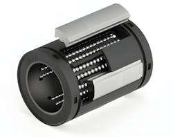
In contrast, linear ball bushings are considerably more forgiving as a linear motion guide option, owing to their design and construction. Dating back to the 1940s, the design of traditional ball bushings features multiple ball bearing raceways and retainers sandwiched between a metal outer cylinder (acting as the out race) and a round guide rail (which functions as the bearing’s inner race). Since there is only point load contact between the ball bearings and both the rail and the outer race, friction is kept to a minimum.
So, while ball bushings aren’t generally as precise or heavy load bearing as profiled rails, they do provide exceptionally smooth motion, even in less-than-ideal conditions. For example, ball bushings don’t require support along the length of the guide rail. As a result, the motion path can be defined only by two anchor points: the span between points bridges over any irregularities in the mounting surface.
Of course, the longer the unsupported span, the larger the rail diameter required. Generally speaking, manufacturers suggest a span no longer than 12 to 24 times the diameter of the rail for closed type bushings. For longer runs, open type linear ball bushings leave an open segment in the cylindrical bushing to accommodate any number of supports along the shaft’s length, while still allowing the bushing some rotation about the rail.
Ball Bushings vs. Profiled Rails
Unlike profiled guides, ball bushings aren’t restricted to linear travel only. They can also rotate, or roll, about the guide shaft so that if one rail is slightly higher—due to uneven mounting surface, or deflection of one rail under load—the bushing allows its enclosure (such as a pillow block) to roll to accommodate the misalignment.
First introduced in the 1970s, self-aligning ball bushings improve the design of the traditional type to boost both load capacity and alignment error tolerance. For example, self-aligning ball bushings are composed largely of a lightweight engineered polymer, to reduce inertia, but also incorporate floating metal load plates that act as the bushing’s outer race.
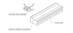
Load plates typically feature conforming grooves slightly larger than the ball bearings to better distribute load forces across the rolling elements, and thereby increase the load capacity of the ball bushing.
READ MORE: Eight Red Flags to Avoid for Longer Ball Screw Life
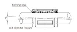
Floating load plates also improve alignment error tolerance, allowing for irregularities in pitch and, in some models, yaw as well. This is due to the force plate’s shape, which has a tapered thickness at each end and a pivot point, or crown, in the center. When installed in an enclosure, the force plate’s crown acts as a pivot point, allowing the force plate to rock back and forth if needed. In operation, this provides up to 0.5 deg. of pitch self-alignment.
One potential issue is that a crowned force plate may grind into the inner bore of the enclosure, eventually reducing the bushing’s self-aligning capabilities. To counteract this, some self-aligning models feature a thin metal band wrapped around the bearing’s outer cylinder.
In this design, the crown presses against the band rather than the enclosure bore. In addition to ensuring pitch alignment over the life of the bearing, the band may also allow the force plates to twist side to side, providing yaw alignment as well.
How Self-Aligned Ball Bushings Improve Performance
Beyond alignment issues, self-aligning ball bushings are also more tolerant of contamination than many other linear motion options. This is due to the design of the ball bushing’s end seals, which also float within the assembly. If the bushing does encounter a misalignment, the seals remain in tight contact with the round rail but, since they can shift slightly in any direction, don’t introduce resistance or drag during travel.
Of course, the two most important factors in linear guide selection are load capacity and the ultimate travel life of the component. Even though ball bushings typically don’t handle loads as high as other options, some manufacturers have begun to push the upper limit.
NB Corp’s recently released Topball Ultimate line, for example, provides 1.3 times the load rating and 2.2 times the travel life of its standard self-aligning TOPBALL series, the company says. In addition, the new model provides four times higher load rating and 64 times longer travel life than its traditional non-self-aligning SLIDE BUSH type.
READ MORE: 5 Essential Facts About Ball Splines for Engineers
The Ultimate line includes the same design elements as other self-aligning ball bushings (e.g., floating force plates and seals) but improves upon it with precision machined races in the force plates and twice the recirculating ball bearing raceways—10 in total for the closed type and 8 for open types—than the company’s standard TOPBALL line.
Available in four Imperial sizes, the line’s dynamic load rating ranges from (C100 max) 1850N (416 lbf) for the smallest bushing to 7570N (1701 lbf) for the largest size. Static loads (C0 max) range from 2060N (463 lbf) to 7430N (1670 lbf).
Factors That Affect Ball Bushing Load Ratings
It’s important to remember that listed dynamic load ratings are dependent on a number of factors, including required bearing travel life, bearing orientation relative to the load, travel speed, rail hardness, lubrication, and environment conditions like temperature and contamination. Less-than-ideal conditions will require designers to derate bearing load capacity, not including any safety factor.
First, dynamic load ratings are calculated relative to 100,000 meters (C100) or 50,000 meters (C50) of travel life before the system (e.g., rolling elements, force plates) sustains sufficient damage to impair application performance. Therefore, a linear motion application requiring more than 100,000 meters of travel life before replacement would necessitate a lighter load than the maximum rating.
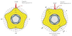
Another limiting factor is bearing orientation. Load ratings assume the bearing is oriented on the rail such that the load is spread over multiple bearing raceways. In the case of self-aligning ball bushings, optimal orientation would orient the bearing so that the force falls between two raceways rather than directly over, or biased toward, one.
READ MORE: Linear Bearing Design Considerations
Similarly, the texture and the hardness of the metal that the round rail is composed of needs to be factored in. A very smooth machined rail, for example, will receive and impart less incremental damage than a rail with a rougher surface.
Likewise, rails made from case-hardened carbon steel will bear up under heavier loads, or facilitate a longer travel life, than 440C stainless steel; however, the latter would be an appropriate choice for corrosive environments. In addition, insufficient lubrication or a high environment temperature can also require engineers to derate the travel life/load rating of a linear system.
As well as dynamic load rating, designers may also have to factor in bearing static load rating (C0). In linear motion applications where the load spends part of its full travel at a slow speed or comes to a complete stop for a period of time during the cycle, those sections or points on the rail will experience increased time under load, and therefore accelerated wear and tear.
Subtracting the sum total of all these derating factors may involve some educated guesswork. However, manufacturers often provide extensive usage guides and online calculators to help engineers better pinpoint the correct ball bushing size and performance for their application.
About the Author

Mike McLeod
Senior Editor, Machine Design
Mike McLeod, senior editor of Machine Design, is an award-winning business and technology writer with more than 25 years of experience. He has covered the full spectrum of mechanical engineering, from industrial automation, aerospace and automotive, to CAD/CAE, additive manufacturing, linear motion and fluid power.
Voice Your Opinion!
To join the conversation, and become an exclusive member of Machine Design, create an account today!

Leaders relevant to this article: