Engineering for Extremes
Key Highlights:
- Proper guideway selection, such as cam follower systems, enhances durability and simplifies maintenance in harsh industrial environments.
- Analyzing moment arms and dynamic loads is crucial for ensuring components can withstand amplified forces during high-speed operations.
- Structural foundations must be engineered as active system components, with concrete strength and site considerations tailored to heavy automation needs.
Enjoying Machine Design’s Motion Control content? Be sure to check out the rest of our Takeover Week coverage here.
Industrial automation is rapidly transforming at a scale unimaginable 20 years ago. Robots with payloads deemed “heavy” in the past are now tasked with moving two metric tons or more. At the same time, work envelopes are expanding from compact, stationary cells to cover much larger areas, sometimes reaching entire factory bays.
This shift toward ultra-heavy automation has unlocked new possibilities in industries such as aerospace, automotive, energy systems and heavy fabrication; but it has also fundamentally changed the engineering assumptions behind motion-system design.
Proper engineering becomes the dominant success factor. Whether the motion solution is custom or an ultra-heavy payload standard product, engineering and design must deal with the extreme loads, harsh environments and high precision requirements.
The margin for error in motion engineering effectively disappears with these increased demands. Longer moment arms need to be able to compensate for the additional stress and forces. Service and maintenance that were once inconvenient can now halt production for days at a time at a cost of thousands or millions of dollars.
Integrating linear motion solutions at this scale relies heavily on three core pillars of engineering: designing guideways and components to address additional demands; rigorously analyzing moment arms and dynamic loads; and treating the structural foundation as an active component of the motion system rather than passive support.
Built for the Trenches
Linear guidance selection is one of the most crucial decisions in ultra-heavy motion design, but all too often the approach uses assumptions drawn from smaller, cleaner automation environments. Traditional profile rail systems rely on small recirculating bearings running on angled contact surfaces.
In clean, controlled settings, these systems can deliver excellent accuracy and stiffness; however, ultra-heavy loads introduce issues such as small alignment errors compounding over distance and uneven load sharing across the bearings, causing premature failures.
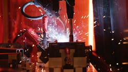
Harsh industrial environments offer additional challenges. Welding spatter, machining chips, metallic dust, carbonized debris and thermal cycling, among other things, introduce contaminants that degrade exposed bearings. Once debris enters a profile guide, the bearing can transition from rolling to sliding contact, accelerating wear and often leading to catastrophic failure.
Cam follower-based guideway systems approach the problem differently. They use large-diameter, sealed rollers running on rectangular rails. The larger surface contact provides a critical “roll-over” advantage: Fine debris that would seize a conventional profile bearing can often be rolled over without interrupting motion. Sealed cartridge designs further isolate the bearing surfaces from contamination, reducing one of the primary causes of premature failure in harsh environments.
From a maintenance standpoint, the difference becomes even more pronounced. In an ultra-heavy robot application, replacing a failed profile bearing may require removing the robot, disconnecting services, lifting the carriage with a crane and re-teaching every programmed path after bearing replacement.
Cam follower systems engineered with cartridge-based rollers allow individual bearings to be replaced in a matter of minutes without disturbing the robot or its calibration. When payloads reach multiple tons, designing for serviceability is not optional; it is a necessity for acceptable Mean Time To Repair (MTTR). Replacement of damaged profile bearings can cause shutdowns extending for days or even weeks.
Taming the Beast
One of the biggest challenges in large-scale automation is underestimating the effect of moment arms. A 2,000-kg payload mounted at the end of a three-meter robot arm does not simply exert 2,000 kg of load on the mounting interface. It generates much larger forces through speed, leverage, acceleration and deceleration.
Every component—bearings, gearboxes, fasteners, weldments and structural steel—must be rated for these amplified dynamic forces, not just the static payload weight. This includes accounting for emergency stops, path changes and multi-axis coordination where the combined forces are amplified over the whole system.
Increases in scale still require the precision of smaller applications. Many ultra-heavy applications still demand repeatability on the order of ±0.02 mm, even while managing multi-ton dynamic loads. This level of performance requires highly rigid guideways, well-engineered control over the cumulative tolerances and bearing systems designed for long life under real operating conditions, not catalog assumptions.
The Ground Truth
When designing ultra-heavy automation, the factory floor becomes a functional component of the motion system. Inadequate foundation specifications become another failure point. Once installed, these shortcomings are difficult to correct.
Heavy robot tracks and gantries concentrate loads on the floor that demand specific foundation characteristics. As a baseline, concrete strength should meet or exceed 4,000 psi and may require a thickness of 13 in. or more. Input from local civil engineers will dictate the site requirements. Those requirements must consider the robots’ operation including loads, quantity of carriages, location of the track and robot orientation, among other factors.
Overhead Logic and Levitation
As payloads increase and floor space becomes more constrained, engineers are rethinking how motion systems are deployed within the factory.
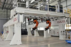
Overhead motion architecture offers one compelling solution. By mounting robots in inverted or elevated configurations, overhead track systems can free 30–40% of valuable floor space while maintaining high precision. Placing mechanics above the process also removes critical components from heat, dust and debris, improving reliability in harsh environments.
Other, non-standard solutions can be implemented in some cases. In an extreme example, a modular air-bearing-based track system demonstrates how extreme flexibility can be achieved beyond embedded rails. Using low-pressure air bearings to “levitate” multi-ton robots allows repositioning without permanent floor tracks, enabling reconfigurable automation layouts at large scale.
The Reliability Blueprint
Ultra-heavy automation changes the rules of motion engineering. Success depends on prioritizing environmental resistance and serviceability from the outset, not after the fact. Guidance technology must be selected based on real operating conditions, not idealized assumptions. Moment arms and dynamic loads must be rigorously analyzed across every component in the system. And structural foundations must be engineered as integral elements of the motion architecture.
As manufacturers face labor shortages and production innovations increase the weight and dimensions of payloads, ultra-heavy automation is no longer a luxury—it is a strategic necessity. At this scale, system reliability is not achieved through redundancy alone, but through deep engineering analysis of bearing life, structural integrity and dynamic performance under real-world conditions.
About the Author
Mike Peek
Robotics Marketing Manager, Güdel
Voice Your Opinion!
To join the conversation, and become an exclusive member of Machine Design, create an account today!

Leaders relevant to this article: