How do Rack-and-Pinion Drives Stack up Against Other Linear Motion Systems?
This article was updated March 29, 2023. It was originally published Feb. 1, 2010.
RELATED
Comparing Performance and Efficiency of Linear Motors, Ball Screws and Rack-and-Pinion Drives
Separating Rack and Pinion Myths from Reality
Lubricating Rack-and-Pinion Sets for Long Life
Linear motors and ball-screw drives seem to hog the limelight when it comes to linear motion. Rack-and-pinion drives, another type of linear motion device, get no respect. But they are perfectly capable of competing with the other two “stars” and have their own advantages. And regardless of what some engineers might have heard, it is not a technology that belongs in the past.
Here's a look at what rack-and-pinion drives can do for engineers who might be dealing with linear-motion challenges.
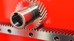
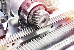
Rack-and-Pinion Features
New-generation rack-and-pinion drives offer high dynamic performance and unlimited travel distances. Some use high-grade servo gears and actuators with backlashes of less than 1 arc-min. and efficiencies of up to 98.5%. Some preassembled gear-pinion units can even run true to 10 µm for smooth, accurate motion.
Many of these advanced features and benefits stem from technological advances made in a broad spectrum of industries. For example, state-of-the-art machining and grinding have greatly improved the precision of rack-and-pinion drives.
Another example of a tech upgrade for rack-and-pinion drives are the high-end racks, the row of teeth the pinion gear rides over. Some are laser etched so that the cumulative pitch error is just ±12 µm over a 500-mm length. This lets operators manually adjust target accuracy. This is useful for precisely synching the motion of a pair of racks. (Two rack-and-pinions in parallel are used to move a single assembly such as a gantry.)
Accurately machined racks also let some machines run without external feedback devices; in contrast, other linear systems need expensive and often complex feedback devices for positioning and coordination.
If noise needs to be kept to a minimum, using a helical rack with an intelligently chosen helix angle might be the answer. They are noted for running quietly at high speeds and having a higher load carrying capacity, all thanks to the helical rack’s larger tooth contact ratio. And single-pitch errors between helical teeth can be as low as 3 µm.
Helical gearing engages smoothly and quietly. This improves the surface finish of parts made on machines that use a helical rack-and-pinion to move the cutting tools.
Modern machining also lets gearmakers adjust the pinion gear’s profile. This is helpful when all the teeth of the gear are not made correctly, a problem prevalent on gears with relatively few teeth. In such cases, the machining method removes too much metal and the root of the tooth is thinner than it should be, or undercut.
To solve this problem, gearmakers carry out profile shifting, adding or subtracting metal to get the proper shape, which bumps up its load capacity.
Rack-and-pinion drives give engineers plenty of design flexibility for getting the performance and control that matches their application’s needs. The design team can use different pinion sizes, gear ratios and damping levels.
Rack-and-pinion drives do have their downsides. For example, putting the pinion and rack teeth too far apart causes backlash, which lowers precision. And misaligned mounting can damage the gearbox bearings, which leads to higher motor currents, noise, and even failures. To avoid these pitfalls in many applications, the pinion should be properly distanced from the rack and the rack should the mounted on a flat surface and perpendicular to the gearbox to within about 25 µm.
Rack-and-pinion drives can be preloaded to eliminate backlash and increase stiffness. To do this, two pinions run on the same rack. The master pinion drives the mechanism while the slave pinion generates torque to counter opposing forces on the teeth it engages. This lets inertia and resistance prevent backlash, even during load changes. It also increases the drive’s rigidity and boosts control dynamics. The slave pinion does oppose the linear motion, so efficiency falls a slight bit.
Linear Motors
Rack-and-pinion drives have performance characteristics similar to those of linear motors but cost much less. They are also smaller and less complex. Linear motors have efficiencies of up to 90%, although sometimes it's considerably lower. Because of this inherent inefficiency, linear motors often need water cooling.
In comparison, rack-and-pinions need no cover, withstand exposure to metallic particles, and there are few applicable safety restrictions. Better rack-and-pinion sets do not require expensive linear scales and external brakes; standard motor feedback and brakes are enough.
Ball Screws
Rack-and-pinion drives accelerate loads faster than ball screws and can maintain higher speeds than them. Rack-and-pinion drives are also stiffer, for better accuracy, and that stiffness remains more consistent than that of ball screws. Rack-and-pinion sets have higher efficiencies than ball screws. Ball screw efficiency only reaches 90% or so while rack-and-pinion sets deliver efficiencies to 97%.
Ball screws have more components than rack-and-pinion drives, making them more prone to failure and more complicated and time-consuming to assemble.
One of the major advantages of rack-and-pinion drives over ball screws (and linear motors) is their unlimited length. An engineering team can run them as far as factory space will allow, and the only additional cost is just that of adding additional racks.
A significant downside of ball screw accuracy is the cumulative errors that can be run up over the travel length. For example, deviation over four meters of travel for a rolled screw drive varies between 300 and 1,700 µm. Even higher-grade ground ball screws have deviations over four meters of between 30 and 110 µm. Two paired rack-and-pinion systems have cumulative errors for the same travel length of only 12 to 40 µm.
Finally, unlike rack-and-pinion drives, ball screws can only handle one load carrier per linear axis and are not suitable for short-stroke applications.
Mike Anselmo was manager of application engineering at Wittenstein Inc. when this article was originally published.
About the Author
Voice Your Opinion!
To join the conversation, and become an exclusive member of Machine Design, create an account today!

Leaders relevant to this article: