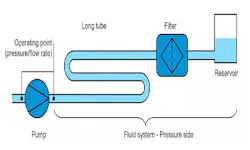
Your country is not included? Please visit our global website Language The Interaction of Pump and Fluid System How customers can find the suitable low-pulsation pump for their fluid system The following blog post provides more information on the interaction of pump and fluid system, and the prediction of pressure loss and operating point. Where the pressure in a fluid system gets "lost" The basis for a reliable prediction is a closer look at the "pressure loss" topic: Each component in a fluid system, such as tubes, installations, filters, elbows or connections, generates a pressure loss when being flown through. These components represent a resistance to the flow. To overcome the hydraulic resistance, the pressure in the fluid must be higher at the inlet of these elements than at their outlet. Figure 1: Example of a flow and the corresponding pressure loss in a fluid system with resistance Other important terms are steady and unsteady flow. "Steady" means that the flow is continuous and thus the average flow rate does not change time-wise. In contrast, the flow rate varies with unsteady flow. A typical example for unsteady flow is the pulsating flow with single-headed diaphragm pumps. Depending on whether the diaphragms are sucking in or discharging liquid into the pressure line, the flow rate in the pipe significantly changes. Reliably predicting the pressure loss in a fluid system The pressure loss in a fluid system depends on various factors. It is also very complex in its calculation. If developers of fluid systems require a quick estimate on the pressure loss in their fluid system, they are confronted with complicated formulae. Online calculators like pressure-drop.com/Online-Calculator may support them. These tools provide users who do not know the respective formulae with a scale on the pressure loss in a specific component. Online calculators, however, are only suitable for steady flows. They are not suitable for pulsating flows as the occurring wave phenomena cannot be considered with their respective formulae. Find out more about the wave phenomenon here. Learn More A fluid system comprises of several components. The following figure shows an example of a pump with a simple fluid system on the pressure side consisting of a long tube, a filter and a reservoir. Figure 2: Pump and fluid system on the pressure side consisting of components The pressure loss depends on the flow rate. If the flow rate in the system rises, the pressure loss increases. For an entire fluid system this results in a characteristic curve that indicates the pressure loss depending on the flow rate (see fig. 3). This characteristic curve is called system curve. In addition to the flow rate-dependent pressure loss, there is also a static part in case of positive pressure in the pressure reservoir or if the pressure reservoir is more elevated than the suction tank. Figure 3: System curve The system curve only characterizes the fluid system. The pump, however, is characterized by the pump curve that can be found in the data sheets from the pump manufacturer. It illustrates the pump’s flow rate with different back pressures. The operating point: A combination of pump curve and system curve To obtain the operating point, the pump curve and the system curve must be combined. Figure 4 illustrates how this happens for a pressure-side system (see fig. 2). The suction side is not considered here. Figure 4: Chart with different pump and system curves that result in the operating points 1 to 3 in their intersection points The pump manufacturer measures the pump curve and will illustrate it on the data sheet. But how does the system curve arise? As mentioned above, the system curve can be calculated. This is already somewhat complex with simple systems as all components in the fluid system must be correctly covered. As an alternative, the pressure can be measured using a low-pulsation pump with a known curve in the system at different rotational speeds. Based on the results, the customer can be recommended a suitable pump for his fluid system. This can be specifically adjusted to the customer requirements. How to make flow rate and pressure in the fluid system predictable A good prediction of the operation point is currently not possible using common pulsating displacement pumps. As already outlined in the first article of this blog post trilogy "A Train Analogy: Flow and Pressure Waves in Fluid Systems", due to wave phenomena in the tubes of a fluid system, pulsation leads to widely varying pressure losses. To counteract this phenomenon, KNF developed the new FP pump series with low pulsation. The pump series offers benefits to the users, such as low pressure loss, a gentler handling of fluids and components as well as less vibration with a lower noise level. But there is another important aspect for the users: Thanks to the low pulsation, the flow is almost steady and the estimations on pressure loss and operating point outlined in this blog post can be applied. The pump’s behavior in the customer system with regard to pressure and flow rate is predictable and the pump in the fluid system can be optimally regulated as required. Find more information on this topic in the other two parts of our blog post trilogy at the end of this article. The most important points at a glance The new FP pumps from KNF provide an almost constant – that is, non-pulsating – flow rate. With regard to pressure and flow rate, the behavior of the FP pump will be predictable in the customer system. We will be glad to offer you a solution that is specifically tailored to your needs. Our KNF experts look forward to your first contact. Related Blog Posts Contact Us Do you want to find out more about our customized pump solutions and service opportunities? Get in touch with our local sales representatives.