3D Printing Tips and Techniques: Printing the First Layer
The following article is a continuation of our series of tips and techniques to help answer your questions about 3D printing. If you would like to contribute tips, or have questions about 3D printing, email me at [email protected].
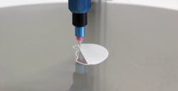
For fused filament fabrication (FFF), properly printing the first layer is important. Often blue painter’s tape is said to be beneficial for making part removal easy and to help the first layer stick. However, if the bed is heated, the tape may not stick. Tape peeling from the build tray or overlapping can provide an uneven surface, which can cause dimensional instabilities and other problems. Also, using a heated bed, even for materials that do not require one, slows the cooling rate. This can prevent excessive shrinking, warping, and delamination from the build tray. Here are some suggestions to help you make the first layers stick.
- Check operating temperatures: Different materials have different melt and glass transition temperatures. Even switching can alter these temperatures. Heating elements in the bed may not achieve the proper temperatures. Putting a cloth or thermal insulating material over the bed until you are ready to print can help get those few extra degrees that might make the difference in firs- layer quality.
- Check the build tray: Make sure the build tray is clean. Oils or small debris can affect the adhesion of the first layer.
- Level the build tray: An offset build tray can cause not only a poor first layer, but can cause the print to fail completely later in the printing process.
- Turn off the fan: This will help to reduce rapid cooling that can lead to poor bonding
- Surface finish: Hairspray and sandpaper can help parts stick to the build tray, but there is another way. This technique comes with a caution as it can weld the part to the surface of the build tray if not done properly. Using acetone on a failed print and wiping the print on the build-tray surface will put down a layer of the polymer you are about to print with, and provide an easier surface to stick to. A little acetone and a light layer to keep parts from becoming welded to the build tray.
- Slow the printer speed for the first layer: It is not desirable to slow the speed, but it can help ensure the material is properly heated and pressed into the build tray.
- Use the brim feature: Brim is when a larger base layer is printed like a base flange around the base geometry that provides more surface area to be in contact with the bed. This can help the print to stick to the build surface and reduce warping. This is also suggested for tall prints with minimum surface contact with the build tray.
- Adjust the Z-offset or flow rate: By adjusting your Z-offset you can flatten the first layer, increasing the contact surface between the first layer and build tray. This can be done by increasing the flow rate. However, adjusting the flow of material may cause more problems with accuracy, and may not allow the materials to reach proper temperatures. Adjusting the Z-offset is preferred. After making adjustments, watch the print to see if the nozzle is dragging through the material. Dragging is a sign that the offset or flow is not set properly, and can also contribute to poor adhesion and poor prints. This technique is like adding a small brim on the part without turning on the feature. If this works you may want to consider a brim. Make sure the adjusted properties are only for this first layer otherwise it could result in a poor or failing print.
- Thicker first layer: Making a thicker, or lower-resolution, first layer can be great in case you are printing on an uneven surface, on top of an existing piece, or have problems removing it from the build tray. Thicker layers allow extra material for post processing to fix any surface finish problems that might have occurred during removal. Again, make sure the adjusted properties are only for this first layer.
Out of Tolerance
There are several things to consider if a print is out of tolerance after calibration.
When 3D printing holes, the tolerance can be smaller than desired for several reasons. First, the edge of the hole isn’t a curved arch forming a circle. The mesh program has formed a series of straight-lined polygons that make up a circle. Design holes with this in mind and purposely making holes a series of small straight lines that form a circle might help. Second, often interior corners and curves can be inaccurate due to the nature of a FFF. Any turn will inherently have more material on the inside and less on the outside, and that may lead to inaccurate interior corners, curves, and holes. Mesh resolution can be increased to help this, but it will also increase rendering and print times.
Perimeter dimensions: Make sure the software knows what nozzle is used. If the software is taking a dimension from the centerline of the nozzle, changing the nozzle size without adjusting the software will result in the dimensions being wrong. Draw a line with the 3D printer. If you have a 10 mm line that prints to be 10.4 mm, check what nozzle you are using versus the nozzle thickness programmed in the printer’s software. Subtracting the dimension of the nozzle from the print is a bad practice. Altering dimension may cause more dimensional or alignment problems if other features are measured from a different datum. Take some time to learn how to make the software work for you. This will save headaches and prevent defective parts.
The Importance of Tolerances
A general idea for assemblies is if 3D printed parts are going to work with preexisting parts and assemblies, tolerances of 0.1 mm should be maintained. Remember, geometric dimensioning and tolerance (GD&T) errors can become magnified over multiple parts or distance. A small tolerance error may cause a catastrophic error later. When working with curing plastics susceptible to warping and shrinking, GD&T can be critical. Tolerance stack up is increasingly important for complex assemblies. GD&T and assemblies are important things to think about when considering a process to use, or printer to buy. If a post-process could work with a printer, the materials and labor needs to be factored into the part.
About the Author
Jeff Kerns
Technology Editor
Voice Your Opinion!
To join the conversation, and become an exclusive member of Machine Design, create an account today!

Leaders relevant to this article: