Comparing Performance and Efficiency of Linear Motors, Ball Screws, and Rack-and-Pinion Drives.
Authored by: Andrew Stock Edited by Kenneth J. Korane Key points: Resources: |
Linear motors, ball screws, and precision rack-and-pinion gear drives are all good options for engineers designing electromechanical linear-motion systems. Rack-and-pinion drives have the longest history — used in elevators in the 1800s, railways in the 1700s, and 16th century crossbows. So one might be tempted to consider rack-and-pinion drives as dated technology.
That would be a mistake. Given advances in precision manufacturing and the recent advent of electronic preloading, the accuracy and performance of rack-and-pinion drives matches or exceeds that offered by competing hardware. And rack-and-pinion units often top the others in terms of durability, efficiency, and economics. Here’s a look at how these drives compare.
Ball screws
Ball and leadscrews have been around for years and are used in all types of industrial applications. Among their advantages over other linear drives, ball screws are economical for short travel lengths, so they’re often preferred for applications such as Z-axis drives. And leadscrews and high-lead ball screws can be nonback drivable — meaning a vertical-axis load will lock in place and not fall if power fails.
On the downside, ball screws can be treated as large springs sensitive to jerk (change in acceleration) and to impact loads that can cause damage and harm performance. The design also limits acceleration and deceleration capabilities and maximum output force.
Maximum length is another limitation. Ball screws mount to a structure at both ends, as there is really no good support mechanism anywhere else. So as travel length increases, unsupported length grows, the screw sags, and performance suffers. Maximum axis length is typically around 6 m.
And a screw’s linear stiffness is not constant but depends on nut position, which can create headaches in dynamic applications. Eliminating lost motion or backlash in ball screws usually requires preloading, incurring more friction, power loss, and potential for abrasion.
By design, a ball screw has a series of ball bearings that travel and recirculate through the nut and screw, lubricating the balls and evenly distributing load, friction, and wear. However, this can make screws noisy. And short-stroke applications prevent complete recirculation of the balls. In such cases, dynamic loads must be derated.
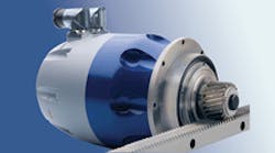
Linear motors
Linear motors became popular in the 1980s with rapid technical advances and the introduction of many innovative products, though the pace of development has tapered off of late. A prime benefit is the moving carriages of linear motors typically have low mass, permitting high acceleration rates and peak speeds. It also saves time when motion frequently changes direction. Brushless linear motors run quietly and the drives typically have long lives.
On the downside, despite improvements, linear motors are still rather inefficient — energy consumption is up to five times that of similarly rated rack-and-pinion actuators. Higher energy demands may mean larger up-front infrastructure investments for high-power lines, transformers, and electrical drives. And linear motors generate a lot of heat and often need a secondary cooling system, which adds cost and complexity and further hurts overall efficiency. Heat generation can be extreme in low-speed, high-force operations, such as drilling.
Because they are direct-drive, linear motors cannot take advantage of gear reduction. Gearboxes are commonly used to match a rotary motor’s speed and torque to the load. With a linear motor, that’s not possible and it sometimes leads to a less-efficient system.
From a closed-loop control standpoint, external loads that induce position deviations can cause oscillations or resonances. Without the reduction in inertia and damping inherent in a mechanical system, controls issues may surface at the workpiece.
Among other considerations, contamination from metal chips, particles, and even small parts can be a problem due to strong magnetic attraction if the linear motor isn’t protected. And with rack-and-pinions and ball screws, brakes can be built-in to the back of standard servomotors. Linear motors, on the other hand, require an add-on secondary brake that’s typically more expensive.
Engineers should weigh a linear motor’s potentially higher cost and energy use against performance advantages and machine productivity. In some cases, for instance, linear motors cannot reach top speed if acceleration and deceleration distances exceed the total travel distance. This can make the linear motor’s technical advantages a moot point.
Rack and pinion
Recent developments in electronic preloading have boosted overall performance and energy efficiency of rack-and-pinion drives.
Advantages include long-term, backlash-free operation and unlimited travel length. In fact, a significant benefit over other designs is lower costs over long travel lengths. Helical gearing lets teeth engage smoothly and quietly. Smooth running also helps ensure good part quality and surface finish, for instance, when machining tight-tolerance parts. For high-precision systems, single-pitch error between helical teeth can be around 3 µm, and cumulative pitch error only 12 µm/500 mm.
Rather than connecting rack-and-pinion drives directly to workpieces, mechanical-transmission elements let engineers vary gear ratios and pinion size, and add damping that can eliminate closed-loop instabilities. In essence, it gives designers an extra element to tune the system and improve performance and efficiency.
On the downside, the rack must be kept clean and lubricated, and the lube can splash at high speeds.
Rack-and-pinion actuators often have acceleration rates and peak speeds nearly as high as those of linear motors. In many cases, the machine frame and structure — not the actuator — limit peak speeds in rack-and-pinion and linear-motor systems. Ball screws tend to have somewhat lower peak speeds and accelerations.
Rack-and-pinion drives boast efficiencies as high as 97%. In comparison, linear motors generally have overall efficiencies of 85%, though some are considerably lower. Ball screws, depending whether or not preloaded, can have efficiencies up to 90%.
Electronic preloading
Rack-and-pinion linear actuators with electronic preloading are intended for high-end applications that demand accuracy and rigidity despite highly dynamic motion. Examples include high-speed cutting equipment, robot motion platforms, portal milling machines, profile machining centers, and laser-cutting machines.
These actuators use a single rack with two pinions and two motors, working in tandem, along with an electronic controller. They give backlash-free motion while minimizing frictional losses, making them more precise and energy efficient than ever.
Here’s how it works over the four different stages of motion.
Standstill. Electronic preloaded rack-and pinion drives have master and slave axes. At standstill, they generate opposing torque and the restraint, or electronic preload, is at its maximum. The master and slave engage tooth flanks facing in opposite directions to eliminate backlash or “play” in the system.
Acceleration. The controller reduces electronic preload during acceleration. The master axis initiates motion while the slave axis eases the opposing force preload. As the unit accelerates, the slave axis transitions to the opposite tooth flank and both actuators act in tandem, but still without backlash. This is important because traditional preloading does not let both axes work together. Instead, one axis always pushes against the other, creating inefficiencies.
Constant speed. During constant-speed movements, electronic preloading is disabled and both axes work together to carry the load. Inertia and workpiece resistance maintain backlash-free operation.
Deceleration. During deceleration, the slave axis again transitions to the opposite tooth flank, increasing restraint to help slow the load and eliminate backlash. There is no backlash during load changes because the tooth and flanks never lose contact.
Accounting for inertia For instance, systems with a servomotor, coupling, and gearhead tend to have high moments of inertia and low mechanical stiffness. They require a low, robust inertia match — a ratio of the motor inertia to the load inertia of about 1:3 — to perform well. Actuators that eliminate couplings and mount the pinion directly on the motor shaft, in contrast, increase torsional and tilting rigidity and limit backlash. This reduces overall inertia, increases stiffness, and tolerates inertia ratios of 10:1. For the design engineer, this permits smaller motors for the same application and, in turn, smaller cables and drives, less energy consumption, and overall greater efficiency. Here’s a look at the underlying math: Consider the simple system shown in the “Horizontal drive” graphic. For dynamic tasks, torque requirements depend on the entire mass reacting in the drivetrain, so engineers must compare load inertia to motor inertia. With JM = motor inertia, JL = load inertia, and i = gear-reduction ratio, the necessary moment for a given acceleration depends directly on the sum of the moments of inertia, JT = JL + i2JM. The coupling factor λ, sometimes described as the inertia match or mismatch, is a correlation of the external moments of inertia to the moment of inertia of the motor. λ = JL/(i2JM); With torque M = Jα and α = angular acceleration, total power in the system PT and power delivered to the load PL relate as: PT = PL(1 + 1/λ); The “Drivetrain efficiency” graphic shows that obtainable torque with respect to obtainable power is proportional to the mass moment of inertia in the drivetrain. It describes the total inertia in the system that must be accelerated in terms of power and efficiency. Most people would think that a 1:1 inertia ratio would be an ideal match. But looking at the graph, only 50% of the total power is delivered to the load. It’s really an inefficient system. With suitable controls, high stiffness, and low backlash, systems can tolerate higher inertia mismatches and use smaller motors for a given load — transferring more energy directly to the load. In addition to better efficiency, a smaller, less-expensive motor requires less energy to produce the same output. |
About the Author
Kenneth Korane
Ken Korane holds a B.S. Mechanical Engineering from The Ohio State University. In addition to serving as an editor at Machine Design until August 2015, his prior work experience includes product engineer at Parker Hannifin Corp. and mechanical design engineer at Euclid Inc.
Voice Your Opinion!
To join the conversation, and become an exclusive member of Machine Design, create an account today!

Leaders relevant to this article: