How to Size Linear Drives that Avoid EMI
Engineers who have designed motion control systems have most likely worked with pulse width modulated (PWM) drives. These drives are the default choice in most day-to-day motion control jobs, thanks to their stability and availability, as well as the fact that engineers are familiar with their reliable operation. But PWM drives tend to be electrically noisy, generating enough electromagnetic interference (EMI) to make them less than ideal in some high-fidelity motion applications.
These noise-sensitive applications include advanced inspection and metrology tools used in the semiconductor industry, in addition to medical imaging and diagnostic devices. That’s where linear drives come into play. Rather than the continuous voltage switching that defines PWM, linear drives scale input voltages to arrive at a desired currents or voltage outputs. This constant gain-approach quickly yields results—accurate current loops—and eliminates any dead bands at the drive’s zero crossing, giving linear drives an edge in high-precision motion control applications.
The downside of taking this route to better precision will mostly come in the form of heat. Linear drives typically maintain small amounts of power inside the drive circuits, increasing heat. Excess voltage not needed by the motor is also dissipated as heat. To manage these thermal conditions while meeting the application requirements, it’s crucially important that the linear drives be sized correctly. Here’s how:
Define System Requirements
Many factors influence system behavior, so it takes several steps to properly size linear drives to match motion-control applications. The most important variables from a sizing standpoint are: • Peak motor velocity (rpm). • Peak motor torque or force. • Average velocity and torque.
Load characteristics and friction effects are implicit in the motor, torque, and force requirements. The motion profile must also be taken into consideration when calculating peak and average torque requirements. For example, a trapezoidal profile requires constant torque until peak velocity is reached. In contrast, S-curve and parabolic profiles require gradually less torque as the move sequence approaches peak velocity. To determine actual application values, torque must be calculated for each motion profile that will be executed because average torque must be known to determine average power dissipation.
Select a Motor and Drive
Once the motion parameters are defined, it is time to make the initial motor and drive selection. First, choose a motor family that will satisfy peak torque and speed requirements. Next, calculate the required voltage and current for each motor in the system. Then look for a drive that can handle these voltage and current values. Note that required voltage is based on the voltage constant (Ke) and peak speed, while required current is based on the torque constant (Kt), peak torque, and resistive losses. Consult the lookup chart or specification sheet for the linear drive being considered to see if there is a match. If not, either another motor or a different drive will need to be selected.
Consider the following example. From the desired motion profile, you know that:
Peak velocity = 400 mm/s (0.4 m/s)
Peak torque = 1,344 N
Stage mass = 280 kg
Motor Properties:
Voltage constant (Ke) = 163.5 m/s/V
Torque constant (Kt) = 141.6 N/A
Winding resistance (r) = 9.5 Ω
Voltage and Current Requirements:
Peak current required:
Ipeak = Peak torque/Kt
Ipeak = 1344 N/141.6 N/A = 9.5 A
Peak voltage required:
Vpeak = (Ke × peak velocity) + (winding resistance (r) × Ipeak ) + drive overhead
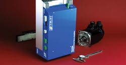
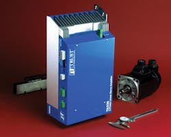
(A10-V safety margin for a Trust Automation TA330/333 linear drive is used in this example)
Vpeak = (163.5 m/s/V × 0.4 m) + (9.5 Ω × 9.5 A) + 10 V = 165.6 V
Bi-polar power supply requirement
1/2 Vpeak = 0.5 × 165.6 V = 82.8 V
In this example, the calculated voltage and current values of 165.6 V and 9.5 A are within the TA333’s capability. (TA333 capability: 25 A and 200 V; TA330 capability: 18 A and 150 V). Vpeak of the TA330 (150 V ) is slightly lower than what is needed, so it is necessary to step up to the TA333 to meet the 165.6 V requirement. This calculation exercise can be done to check the suitability of any linear drive.
Determining the Safe Operating Area
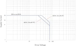
Once the initial linear drive is identified, designers must calculate the safe operating area (SOA), a graphical representation of the voltage and current conditions under which the drive can operate for a given amount of time without damaging itself. Operating the drive within the SOA for the application ensures that the power does not surpass the drive’s capacity to dissipate heat.
Although some linear drives have reactive safety, if SOA is significantly and quickly exceeded, the drive may not be able to shut down in time to prevent damage. Basically, a linear drive acts as large variable resistor in the motor-drive circuit. Voltage to the motor gets divided between the motor and drive with the current in series, using a pair of power devices and the motor. Two of the most common danger conditions—stalls and dynamic breaking and deceleration.
Here are two examples of and calculations of these two danger scenarios; one involves a stalled motor and the other looks at dynamic stopping. Note that the TA330 and TA333 motors in these examples calculate wattage per power device. There are at least two power devices on at any time, so the worst-case wattage is half the total wattage.
Stalled motor. Consider a stalled motor pushing against a hard stop while the controller is commanding 9.5 A.
Known values are:
Total supply voltage (Vsupply) = 192 V
Commanded current (Icommand) = 9.5 A
Motor impedance or winding resistance = 9.5 Ω
Heatsink temperature = 30°C
Calculated Values:
Vmotor = I command × winding resistance = 9.5 A × 9.5 Ω = 90.3V
Vdrive (voltage remaining) = 192 V − 90.3 V) = 101.7V
Wdrive (total wattage the drive must dissipate) = 966.6 W
W per device = Wdrive / 2 = 966.6W/2 =4 83.2 W
According to the TA333 SOA chart that covers wattage, time, and temperature, 483.3 W at 30°C is within the continuous operation zone. Be sure to ask your linear drive manufacturer for the SOA chart or spec sheet that corresponds to the drive you are considering.
Dynamic stopping. Calculating the wattage when motion is involved becomes more complex due to the kinetic energy moving the load. When the controller sends a command to stop moving, the kinetic energy must be dissipated. In traditional PWM drive setups, kinetic energy is pushed onto the power supply bus and a shunt regulator typically dissipates this energy. With a linear drive, the kinetic energy is absorbed by the drive but must still be dissipated as heat. This energy must be added to the energy required by the drive to stop all motion to determine the total amount of energy that must be dissipated.
It is difficult to calculate the exact amount of kinetic energy to be absorbed because system efficiency and friction are large variables that must be considered. For example, an ultra-low friction air-bearing stage may retain close to 100% of this energy, while a high-friction lead-screw stage might only retain 5% of the energy.
In the following example, deceleration is linear, an assumption. Average kinetic energy over the stopping time is used in these calculations and is applied when the motor stops, but the command current will still be going:
Kinetic energy (KE) = 0.5 × mv2 (in joules)
Wattage = (KE/2)/time (assuming linear deceleration)
Adjusted wattage (Wadjusted) = wattage × friction factor
Units:
m = mass (Kg)
v = velocity (m/s)
Kinetic energy (KE) = joules (J)
t = time to stop motion
Friction factor % = estimated energy lost to friction (ff)
Known Values:
Mass = 280 Kg
Velocity = 0.4 m/s
Time = 0.1 s
ff = 90%
Calculated Values:
(KE) = 0.5 × mv2 = 0.5 × 280 Kg × (0.4 m/s)2 = 22.4 J
W = (KE/2)/time = (22.4 J/2)/0.1 s = 112 W
Wajusted = wattage × friction factor 224 W × .9
= 100.8 W
Add the kinetic energy value to the stalled wattage equation for a rough estimate of the wattage the drive needs to dissipate when stopping. This energy must be added to the individual power device wattage because it is not shared energy. From the stalled motor calculations in the previous example, take 483.3 W (worst-case wattage) and add the Wadjusted of 100.8 W to get a thermal load of 584.1 W on the drive. Not all linear drives measure kinetic energy. Nevertheless, it is extremely important for designers to consider these calculations when setting up a motion system.
Calculate Continuous Dissipation
The final step in choosing a correctly sized linear drive is to calculate the continuous operating limits to ensure the average wattage rating is not exceeded. If it is, the drive could be damaged and system performance would be degraded. Keep in mind that average velocity and torque are calculated in relation to time. To keep things simple, assume a trapezoidal motion profile and use half the torque and velocity during acceleration and deceleration.
Using these values, generate a timetable with the system’s torque and velocity for the move profile. Be sure to include all cycle and dwell times. Multiply the time by the torque and sum all steps, then divide by the total time for the average torque value. Repeat with velocity to obtain the average. Next, use these average numbers to calculate wattage in the same manner as the first example described previously.
Average current required (I) = Average torque/Kt
Average voltage required (V) = (Ke × average velocity) + (winding resistance × average current required)
Average wattage dissipated = (Supply voltage – average voltage) × average current
Example:
Supply voltage = 192 V
Average torque = 247.1 N
Average velocity = 0.18 m/s
Using the Selected Motor Properties:
Voltage constant (Ke) = 163.5 m/s/V
Torque constant (Kt) = 141.6 N/A
Winding resistance (r) = 9.5 Ω
Average current required (I) = Average torque/Kt
Average voltage required (V) = (Ke × average velocity) + (winding resistance × average current required)
Average motor current(I) = Average torque/Torque constant
=247.1 N/(141.6 N/A)
= 1.74 A
Average motor voltage (V) = (Ke × average velocity) + (winding resistance × average current required)
= (163.5 × 0.18) + (9.5 Ω × 1.74 A)
= 46.3 V
Total drive W = (Supply voltage - Average motor voltage ) × Average motor current
= (192 – 46.3) × 1.74 = 254.2 W
The final step is to verify the average heatsink wattage does not exceed 400 W with the heatsink at 20°C (for the TA330 and TA333 linear drives discussed). Calculated results must be evaluated against the drive’s SOA chart. In the example used here, calculated peak wattage is 584.1 W for 0.1 s (100 msec).
According to the TA330 SOA chart, 584.1 W in continuous operation corresponds with a heatsink temperature up to 29°C. At 30 to 34°C, the controller would allow 61 msec prior to generating a fault. The allowed time decreases as temperature rises. Therefore, if the heatsink temperature is allowed to climb above 29°C, (driving for 100 msec), the drive could be damaged.
Studying the TA333 SOA chart, 584.1 W in continuous operation corresponds with a heatsink temperature up to 49°C. At 50 to 54°C, the controller would allow 84 msec prior to generating a fault. In this case, if the heatsink temperature is allowed to climb above 49°C, the drive could be damaged.
The tips and calculations described here are intended to help engineers make informed choices when selecting linear drive. Once the actual system is up and running, however, these values should be analyzed again to optimize drive performance.
Dave Rennie is vice president, business development at Trust Automation. For more information, visit www.trustautomation.com.
About the Author
Dave Rennie
Vice President, Business Development, Trust Automation
Voice Your Opinion!
To join the conversation, and become an exclusive member of Machine Design, create an account today!

Leaders relevant to this article: