The same familiar problems. Pick a step motor that’s too big and you’ll end up with vibration. Too small, and it’ll likely stall out. Then there’s rotor inertia. If inertia is too small, you’ll never be able to get the load moving. Truth be told, proper selection and sizing of step motors is not difficult: Just follow a few basic steps.
Acceleration determination
The first order of business is to determine the acceleration rate. All load motion, whether rotary or linear, must be converted into motor motion — the number of revolutions or degrees the motor must rotate. Since you already know how much time is available to achieve the desired motion, you can determine the acceleration rate and peak motor speed.
Be sure to consider rotor inertia as well. As a general rule, load inertia should be no more than 10 times the rotor inertia. For short, quick, high-performance moves, the ratio of load inertia to rotor inertia should be closer to 1:1.
Two-pronged torque value
When determining torque, remember that it’s actually made up of two components — constant torque and acceleration torque. Constant torque Tc usually results from friction and gravity and fights against the motor. In other words, the motor must always overcome this torque. Fortunately, it is easy to measure (applying a torque wrench to the load) or calculate (friction force is μW, where μ = coefficient of friction and W = weight of the load). Once you know the force, it is a simple matter to factor in the radius of action to convert it to torque.
Acceleration force is harder to measure because it is difficult — not to mention dangerous — to simulate an acceleration profile while holding a torque wrench on the load. If the load needs to be up to speed quickly, say 50 msec, the torque wrench is likely to fly off.
Calculating acceleration torque isn’t that complicated, however. Acceleration torque Ta is the product of acceleration a and load inertia Ja. Since the inertia and acceleration rate have already been determined, acceleration torque can easily be calculated.
Once the acceleration torque is calculated, add it to the constant torque, and multiply by a safety factor of about 1.5. You now have a torque value and a peak speed value. At this point, check the torque/speed curve to see if the selected motor can perform the move.
Two kinds of motion profiles
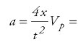
Moves usually take the form “move x distance in y time.” The two types of motion profiles include trapezoidal and triangular. Typically, triangular profiles are used for moves of less than a second and trapezoidal profiles are used for moves greater than a second. Regardless of which type of motion profile is used, it is easy to determine the acceleration a and the peak speed Vp from the following equations where x = total movement and t = total move time.
For triangular profiles:
Once a is calculated, it is multiplied by the quantity of reflected inertia plus rotor inertia to get the acceleration torque, or TA = a(JRef + JR). All step motor rotor inertias are provided in the motor specifications. Once TA is known, add TC, multiply by a safety factor, and since the peak speed has already been calculated, the torque/speed curves can be referred to in order to see if the motor will work.
Example time
Suppose you have a horizontal screw 30 in. long, 0.5 in. diameter, with five threads/in. Suppose also that the load is 75 lb, and you want to move 2 in. during 1.3 sec. For the following equations, c is the efficiency of the screw, (about 0.95 for ballscrews and 0.7 for others); p is pitch; and the equation for the inertia in a long cylinder (i.e., the screw) is:
Then:
Suppose you choose a motor with a rotor inertia of 1.5 oz-in.2 Using a trapezoidal profile, and since 2 in. equals 62.8 rad of motor movement,
So, TTot = 1.5 + 6 = 7.5 oz.-in. and TReq = (7.5)(1.5) = 12 oz-in.
With regard to the torque/speed curve, the motor selected (based on its inertia ratio) is found to have more than adequate torque to do the job. In fact, it has a lot more torque than required. Because excessive torque can cause vibration problems, the current should be lowered, thereby lowering torque.
Craig Ludwick is an application engineering manager for Oriental Motor U.S.A. Corp., Torrance, Calif.
