About phase
Last month we discuss-
ed control loop insta-
bility and how it comes from a "sign reversal" in the loop. This condition is caused by an accumulation of phase and gain around the control loop adding to -1, or a gain of 0 dB at 180°.
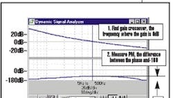
But there's also a numerical measure of stability called phase margin. Phase margin (PM) is a precise method of gaging loop stability. It is measured at a frequency common to all control systems, called the "gain crossover," which is the point where the gain is 0 dB. At low frequencies, loop gain is usually high, while at high frequencies, the gain is low, which is why it's a lot easier to move inertia at low frequencies. Somewhere in the middle frequencies, though, the gain crosses through 0 dB, and this is the gain crossover frequency. Phase margin is the difference, in degrees, between 180° and phase angle at gain crossover. If the phase were 180° at crossover, corresponding to a PM of zero, the system would be unstable. If the phase margin is too low, the system will be marginally stable but it will overshoot excessively and ring. The right amount of phase margin depends on the application, but it usually falls between 50° and 80°.
To measure PM, you need to know the phase and gain around the loop. Let's say, for example, that at a frequency of 60.5 Hz, the phase and gain add up to 0 dB at -114°. This is the gain crossover frequency because this is the point where the gain is 0 dB. Phase margin then, is the difference between the actual phase (-14°-6°-90° -4° = -114°) and instability -180°, in this case, 66°.
So let's use phase margin to understand tuning a little better. Consider our control system. If we increase the gains, we'll have a more responsive system. But a check of the phase margin shows that it can be unstable.
The Bode plot illustration shows two "open loop" gains. The red trace shows the system with the original servo constants and the blue one shows those gains increased by a factor of 4, which is equivalent to 12 dB. Increasing the servo gain this much has the effect of increasing the loop gain by the same amount. This is why the blue trace is 12 dB above the red trace. Thus, raising the loop gain moves the crossover frequency to the right, to about 250 Hz. At 250 Hz, the phase is 140° so the PM falls to 39°, and the system will likely have a tendency to overshoot or ring.
No gain, no pain
A simulation for the system at the left was run on a free stand-alone software package called ModelQ, which you can find on PT Design's website, www.ptdesign.com. After installation, click "Run" and at top left select the May/June model from the combobox at top center.You can generate a Bode plot of the loop gain by pressing "GO" near the center bottom. Click "Open" near the center of the screen to see the "open loop" gain. In a few seconds the Bode plot will appear on the dynamic signal analyzer (DSA). The gain (top plot) crosses 0 dB at about 60 Hz, just as it did in the discussion above. Turn on the cursor and move it to the gain crossover selection of "0 dB" in the combo box next to the magnifying glass and then click on the magnifying glass. Notice that the cursor box shows the frequency, phase, and gain. You'll find that the phase is 115°, indicating a healthy PM of 65°.
Now raise the gain KVP from 0.72 to 2.88, a factor of four (12 dB). Run a new Bode plot and watch as the gain plot moves up 12 dB, pushing the gain crossover out to a higher frequency.
Marginal improvement
Applications that demand the highest performance need to reduce unnecessary phase lag in the system. Any reduction will increase the phase margin, and therefore stability.
In our simple example, just changing the feedback device from resolver to encoder would have helped the PM. The phase loss by the resolver was just 4° at 60 Hz, however, phase lag often grows as frequency increases. The phase lag at 254 Hz from the resolver is 20°. This is one reason why the high-end systems are more likely to use encoders. They add almost no phase lag.
There are other steps you can take to reduce unnecessary phase lag. For example, use high speed current loops and high sample rate digital drives, and take out unnecessary noise filters. Often, in control systems, filters are used to cover over problems like poor wiring or low-resolution encoders. They may cover the noise but at the expense of adding phase lag. Used properly, however, filters can help ensure the best response rate a system can deliver
