The current connection
If you want to control the torque of a permanent-magnet servomotor, you have to go to the source: the current flowing into the coils.
The relationship between current and torque in a PM motor is based on the interaction of the coils' electromagnetic field with that of the magnets. Basically the fields exert a force on each other, producing torque that's delivered through the motor shaft. The path to well-controlled torque, therefore, starts with well-controlled current.
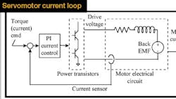
Electric motor drives (also known as inverters or amplifiers) use power transistors to handle electrical energy. The transistors actually control voltage; current is the result of the voltage dropped across the motor windings. Inasmuch as power transistors are voltage devices, a current loop is required to achieve current control.
A typical current loop compares torque (current) commands to the feedback from a current sensor and adjusts the drive voltage accordingly to minimize error. Not all drives use current loops, however. Many just output a voltage, relying on motor parameters to limit the current. This may work in some applications, but it's not intended for high power (> 500 W) or demanding machines.
Controlling torque in a brush motor is relatively straightforward. Torque is approximately proportional to the winding current, related by a parameter called the torque constant KT. With brush motors, the current command is independent of motor position and speed.
In the case of brushless motors, controlling torque is more complicated. Here, current must be switched electronically (commutated) at each motor winding. In addition, brushless motors require sinusoidal current to provide smooth torque. Usually, all this is handled by computer algorithms that determine the right amount of current for each winding based on motor position, speed, and the amount of torque needed at that instant. This method of commutation is complicated enough to warrant a digital signal processor (DSP) or a high-speed microprocessor.
Although the torque of a brushless motor isn't proportional to current in any one winding as with brush motors, similar relationships are present in that the servo loop commands torque and the drive applies voltage. So here again, a current loop is still the best way to regulate voltage in order to produce the currents that make the torque.
A little history is in order to more fully appreciate today's drive technology. When electric servomotors debuted in the 1970s, they were accompanied by analog drives. During the 1980s, drives began to go digital, starting with commutation functions and then velocity loops. Current loops made the switch only recently because they typically require much more compute power. Current-loop update rates, at about 16 kHz, are several times faster than those of other drive functions. The advent of low-cost DSPs, with their blazing computational speed, is what finally made "all-digital" digital drives practical.
Today, if you purchase a drive and motor from a single vendor, you may be spared the unpleasant task of commissioning (tuning) the current loop. Nonetheless, every designer should understand how current loops work because of their potential impact on machine performance.
The first step is to find out what the bandwidth of the current loop is. This is a measure of responsiveness that most drive vendors should be able to provide. Generally speaking, a motion application will work well if the current loop has a bandwidth of at least 800 Hz.
If the current loop isn't fast enough, it will undermine system performance. Being in the middle of the velocity loop, a current loop, in a sense, acts like a filter, providing a delayed response to the velocity-loop output. As discussed in a previous issue (May 1999) this can make the velocity loop unstable. If you have a slow current loop, then, the only way you can achieve stability in the velocity loop is to reduce servo gains -- but that means your machine runs slower.
Current loop analysis is tricky because of the complexity of torque production, which involves commutation, the control of power transistors, and the current loops themselves. As a result, the impact of the current loop on the performance of a machine is not always obvious.
Usually a current loop can be simplified to look like a filter with a Bode plot similar to the loop itself. A current loop on a drive with a bandwidth of 800 Hz, for example, can be modeled as a twopole, low-pass filter with an 800-Hz bandwidth. In fact, the current loop model used in the simulations for this column is just such a filter, with a bandwidth of 800 Hz and a damping ratio z of 0.7. These values will give you a good idea of what to expect from a high-performance servo drive.
Settle down
Ready to take a look at the impact of current loops for yourself? Then log on to www.motionsystemdesign.com and download the free control system simulator, ModelQ.
After installation select the February 2000 model in the combo-box at top center and click "Run." You're now looking at a velocity controller operating in simulation.
Initially the current-loop bandwidth will be high and you'll find that the system does a good job following a step command. As you decrease current loop bandwidth, however, from 800 Hz to 200 Hz, the system becomes less stable. (The bandwidth is defined by the constant CLoop on the left of the screen.) What this should be telling you is that, with a slower current loop, you'll have to settle for a slower machine, or your machine may not settle for you.
Take a pill
Pharmaceutical machines that fill medicine bottles are a good example of a motion system that demands fast response. Such machines are rated, in large part, according to how quickly they can feed pills into bottles. That means having the right controls and the right mechanics, linked by a drive with a sufficiently fast current loop.
George Ellis is Senior Scientist at Kollmorgen Inc., Radford, Va., where he does research and design in motion control. His new book, Control System Design Guide, (2nd Edition), is scheduled to be published by Academic Press later this year. You can contact George at [email protected].
