Linear motors: How to beat the heat
If a linear motor fails, most likely the cause is thermal stress. Unlike their rotary counterparts, thermal stress is the major performance limiting factor in linear motors.
Aside from potential thermal failure, a properly cooled linear motor can produce 50% more force then a linear motor with no cooling. A plot of force versus the square root of temperature difference — the difference between the coil temperature and the ambient temperature — will be 50% steeper for a cooled linear motor then a non-cooled motor.
Electrically, brushless linear motors and rotary motors are identical. The linear motor’s forcer coil (primary) receives electrical current and travels over a permanent magnet secondary section, Figure 1A and 1B. However, the current flows through a smaller area in a linear motor than in a rotary motor, building up more heat faster. Thus, many manufacturers recommend that engineers always choose a motor with a heat sensor in the forcer coil.
Determing cooling requirements
Engineers can also reduce the chances of motor failure through proper motor selection, including determining the cooling requirements. The manufacturer’s motor data usually indicates the maximum coil temperature of a linear motor, Table 1. With this information, the ambient temperature, and the potential thermal stress possible in the application, an engineer can determine whether the linear motor needs cooling and select the most appropriate cooling method.
The first step is to compute the peak and rms force required for the application and choose a candidate motor.
Next, determine the ambient temperature.
After these figures are gathered, the engineer should select a cooling method. Most linear motor designs use one of three cooling methods.
Conduction. As the forcer coil temperature increases, heat flows into the payload table attached to the coil. A large thermal mass can minimize the overall structural thermal rise.
Radiation. Heat radiates from the coil into the ambient air. The ambient air temperature must remain lower than the coil temperature.
Convection. The motor is cooled by forcing air or water through the primary coils. The motor has a port that the user connects to a compressor for forced air. For water, the port is connected on the inside of the motor to tubes that run near the forcer coils. On the outside, the port connects to a forced water system that pumps water through the tubes.
Engineers can select a cooling method by either building a prototype system and taking temperature measurements, or by solving heat transfer calculations. The first method is the most accurate but not always practical. The second method, if done by hand is often time consuming. Engineers can obtain estimates from formulas found in mechanical engineering handbooks.
These formulas* can be solved on a hand calculator and give good approximations of the effectiveness of a candidate cooling method.
For conduction:
q = heat flow rate, W
k = thermal conductivity, W/m
A = area of flow path, m2
l = length of flow path, m
ΔØ = temperature difference between the start and end of the heat flow path
RØ = l/kA = thermal resistance, C/W
The effect of radiation cooling is almost insignificant in practical application. To calculate it, though, use:
A1 = area of surface 1, m2
Ø1 = absolute temperature of surface 1, K
Ø2 = absolute temperature of surface 2, K
For convection:
q = hA (θ1 - θ2)
Where:
q = heat flow rate, W
h = surface heat transfer coefficient, W/m2c
A = effective surface area, m2
Ø1 = surface temperature of the solid, C
Ø2 = temperature of the air or water, C
The most efficient cooling method, and the most expensive, is convection with forced water.
For more precise answers, a few commercial software packages for heat transfer analysis are available.
The next step is to determine the forcer coil temperature the motor may achieve in the application. Information on maximum coil temperature of a specific linear motor is usually found in the manufacturer’s catalogs or specification sheets, Table 1.
Often, engineers have a good idea of how much continuous force the application will require. Information on a motor’s thermal resistance is usually found in the manufacturer’s data sheets, Table 1. To estimate the temperature that the motor’s coil may rise to under specific force and ambient conditions of an application, engineers can solve the following equation. (Most manufacturers rate the continuous force of their motors under these conditions: 25 C ambient temperature, 155 C maximum coil temperature, with forced air cooling.)
Tc = coil temperature, C
Ta = ambient temperature, C
Fc = continuous force
Km = motor constant
Rthm = thermal resistance
Engineers should then derate the continuous force of the candidate motor based on this temperature and coolingmethod information.
For example, suppose an engineer selects a candidate linear motor rated at 42-lb continuous force. However, the application has a maximum ambient temperature of 40 C and requires that the coil temperature of the motor be limited to 125 C. Using the motor constant Km, or 2.4, and the thermal resistance Rthm, or 0.43, from the manufacturer’s data sheet, Table 1, the continuous stall force is limited to:
Tc = coil temperature
Ta = ambient temperature
Km = motor constant
The application’s thermal conditions reduce this linear motor’s continuous force by almost 20%. (Calculated continuous force, 33.7, divided by rated continuous stall force, 42, equals 80%.) Operating the motor at this continuous force will generate nearly 198 W of heat. The engineer must manage this heat transfer into the system.
The last step is to compare the derated linear motor’s continuous stall force to the rms force requirement. In the above example, the derated linear motor cannot meet the rms force requirement, therefore the engineer must either select a larger motor or change the cooling strategy and repeat the derating calculations.
Heat and other motor components
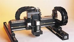
Linear motors are frameless brushless motors and require a bearing system and a mechanical superstructure, Figure 2. There are two basic bearing technologies to hold the forcer coil in the magnet track and guide the linear motion of the motor. Mechanical bearings can be cross-roller or recirculating-ball types. Non-mechanical bearings can be air or magnetic. In general, air and permanent-magnet magnetic bearings are more expensive and complex than mechanical bearings, but are required for some applications, such as semiconductor and flat panel display manufacture.
Except for extreme cases, neither of these bearing technologies add significant amounts of heat to the linear motor.
The most common linear motor feedback device is the linear encoder — a graduated scale that runs the length of travel. Analog comparator circuitry or a digital signal processor can increase the resolution of the encoder. An electronic multiplier with the encoder can achieve system resolution in the sub-micron range.
For resolution less than the sub-micron level, use laser interferometer technology. In such a system, an optical interference pattern is used to achieve nanometer-level resolution. For either feedback sensor, though, heat problems can degrade the sensor and system resolution. Linear scales expand when heated and the interferometer light wave length changes with temperature. Either move the linear scale from the heat source or, if the motor is using forced air cooling, use this system to cool it too. (The engineer will have to recalculate the heat dissipation equations and possibly select another size motor.)
Most amplifiers and controllers designed for rotary brushless motors can also operate with linear motors. Be sure to match the amplifier to the motor.
* Equations from the Handbook of Electric Motors, edited by Richard H. Engelmann and William H. Middendorf, Department of Electrical and Computer Engineering, University of Cincinnati, Cincinnati, Ohio. Published by Marcel Dekker Inc., New York.
Robert Novotnak, Ph.D., is chief engineer and Robert Sobek, is product manager of the Drive Components Group; and Stephen Botos is product marketing manager at Aerotech Inc.
Voice Your Opinion!
To join the conversation, and become an exclusive member of Machine Design, create an account today!

Leaders relevant to this article: