20 Minute tune-up: Put a PID on it
Last month in Tune Up we learned about cascaded position-velocity loops, and we developed a simple procedure for tuning them. This month we analyze another common positioning method, proportional-integral- differential, or PID, control.
A position controller works by comparing position commands to position feedback signals, and then calculating the position error, PE. In a PID loop, this signal is then used to generate the current command based on three gains – PE is scaled by the proportional gain KPP, the integral of PE is scaled by the integral gain KPI, and the derivative of PE is scaled by the derivative gain KPD.
Tuning a PID position loop can be challenging because there are three servo gains and each plays a different role. Once you understand those roles, however, you can tune the gains independently, saving time, ensuring consistency, and maintaining stability with improvements in command response.
As with cascaded position-velocity control, each of the PID position controller gains operates in one of three frequency “zones.” Think of the position command as being composed of many frequency components. The derivative gain KPDP responds to the highest zone, frequency components between about 30 and 100 Hz. The proportional gain KPP addresses commands from 10 to 30 Hz, while the position-loop gain covers all frequencies below that.
The best place to start the tuning process is the highest frequency zone. First eliminate the lower zones by zeroing KPI and, if possible, KPP. Many PID controllers do not allow KPP to be zeroed. If that’s the case, fix KPP at a fairly low value while tuning KPD.
Next, prepare a trapezoidal point-to-point velocity profile. These commands have three segments: acceleration, cruise, and deceleration. When tuning Zone 1, you should set the acceleration and deceleration rates to their maximum controller values. In fact, a square velocity command (unlimited acceleration) is ideal.
If not enough power is available to produce the command response, the controller may saturate, requiring you to lower peak velocity. Usually a top speed of 0 to 250 rpm works well.
The next step is to raise the derivative gain to the highest possible value before overshoot appears in the velocity response. Note that if you cannot zero the proportional gain KPP, expect some overshoot for a square wave. Overshoot from KPD occurs on a much shorter time scale and is easy to distinguish from overshoot caused by KPP. When you have a response with minimal overshoot, your differential gain is tuned.
Zone 1 is the hardest zone to tune mainly because KPD tends to excite resonance (October, 1999) and audible noise (July, 1999). Low-pass filters can offset these effects, but they also cause instability and force servo gains lower.
To tune the proportional gain, first modify the position command. Lower the acceleration and deceleration rates to within the highest values that the controller will employ during normal operation. Raise the integral gain until a slight amount of overshoot is visible, and then decrease KPP to eliminate overshoot. When you reach this point, KPD and KPP are tuned.
The final zone to tune involves the position- loop integral gain. Tuning this gain is difficult because of its high sensitivity to overshooting. Fortunately, several methods have been developed to deal with this shortcoming.
First, many controllers let you clamp the maximum current commanded by the integral term. The primary reason to use integral gain is to overcome frictional loads, thus there is no need for the current generated by KPI to exceed the maximum load capacity.
Another way of dealing with overshoot is to force the integral term to zero anytime the motor is commanded to move. When motion stops, the integral term is reinstated to cover the low-frequency zone. Like the clamping method, this allows higher peak values of integral gain than normally possible.
Tuning with PID
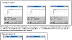
Want to tune a PID position loop yourself? Then log onto www.motionsystemdesign.com and download this month’s ModelQ simulation program. Launch the program, select August’s model, and click “Run.” You should be looking at the response with just the derivative gain (KPD). The value is set a little low (0.6), so raise it until the response signal just overshoots, and then reduce the gain to eliminate the small amount of overshoot (KPD = 1.1).
Next, select a trapezoidal velocity command by choosing “Trapezoid” in the waveform generator at bottom left. Raise KPP to the highest value that does not cause overshoot (KPP = 10), and then raise KPI to 5 to get a complete set of PID tuning gains.
George Ellis is a Senior Scientist at Kollmorgen. His book, “Control System Design Guide,” 2nd edition, was published in May, 2000 by Academic Press. He can be reached at [email protected].
About the Author
Voice Your Opinion!
To join the conversation, and become an exclusive member of Machine Design, create an account today!

Leaders relevant to this article: